Optical image stabilizer

Inactive Publication Date: 2007-01-04
HOYA CORP
View PDF15 Cites 15 Cited by
  • Summary
  • Abstract
  • Description
  • Claims
  • Application Information

AI Technical Summary

Benefits of technology

[0006] The present invention provides an optical image stabilizer having a simple and small structure th

Problems solved by technology

However, since the image-stabilizing optical element needs to be driven at high velocity in a fast responsive manner, such movement tends to be a burden on the driving mechanism therefor.
Namely, the image-stabilizing optical element easily reaches a mechanical limit of movement thereof in the case where the magnitude of vibration is great, and the movement of the image-stabilizing optical element is easily restricted by some other reason.
In such a movement limited state of the image-stabilizing optical element, further application of a driving force to the image-stabilizing optical element causes a driving force transfer mechanism for the image-stabilizing optical element to be subjected to mechanical stress and thus may cause damage to a low-strength portion of the driving force transfer mechanism.
Additionally, in the case where the image-stabilizing optical element is supported by a support mechanism at all times to be freely movable, there is a possibility of the image-stabilizing optical ele

Method used


Image

  • Optical image stabilizer
  • Optical image stabilizer
  • Optical image stabilizer

Examples


Embodiment Construction

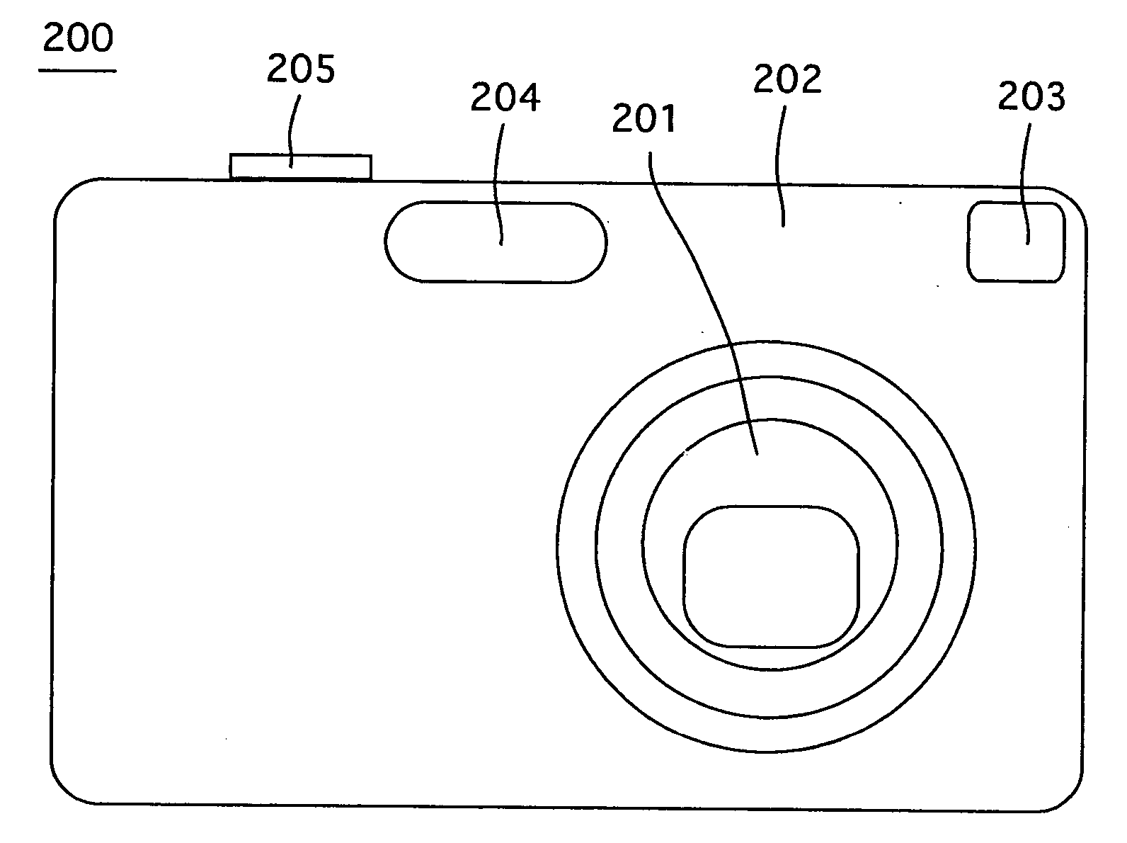
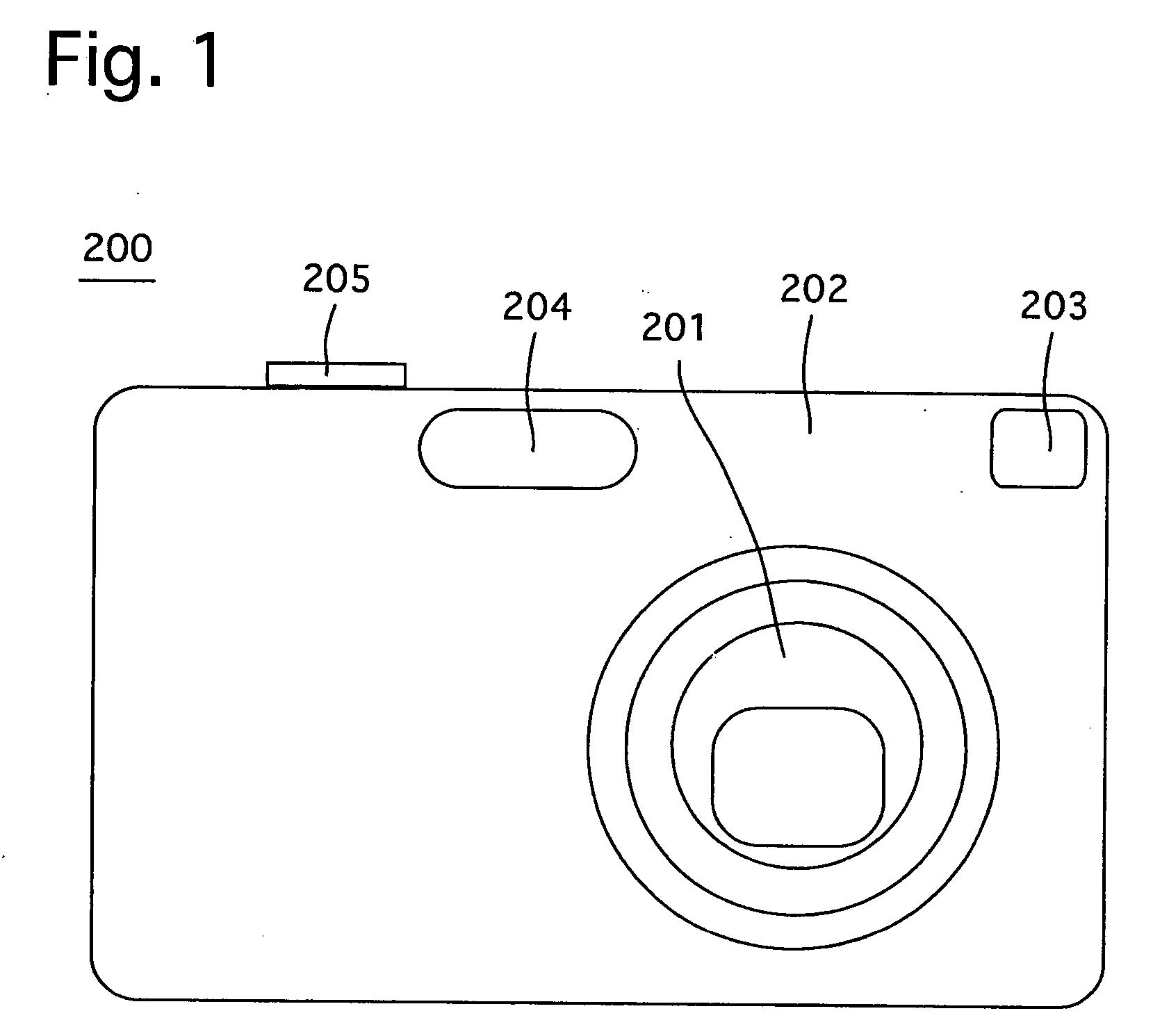
[0056]FIG. 1 shows an outward appearance of a digital camera 200 which incorporates an image stabilizer according to the present invention. The digital camera 200 is provided on the front of a camera body 202 thereof with a zoom lens (zoom lens barrel) 201, an optical viewfinder 203 and a flash 204, and is provided on the top of the camera body 202 with a shutter button 205.

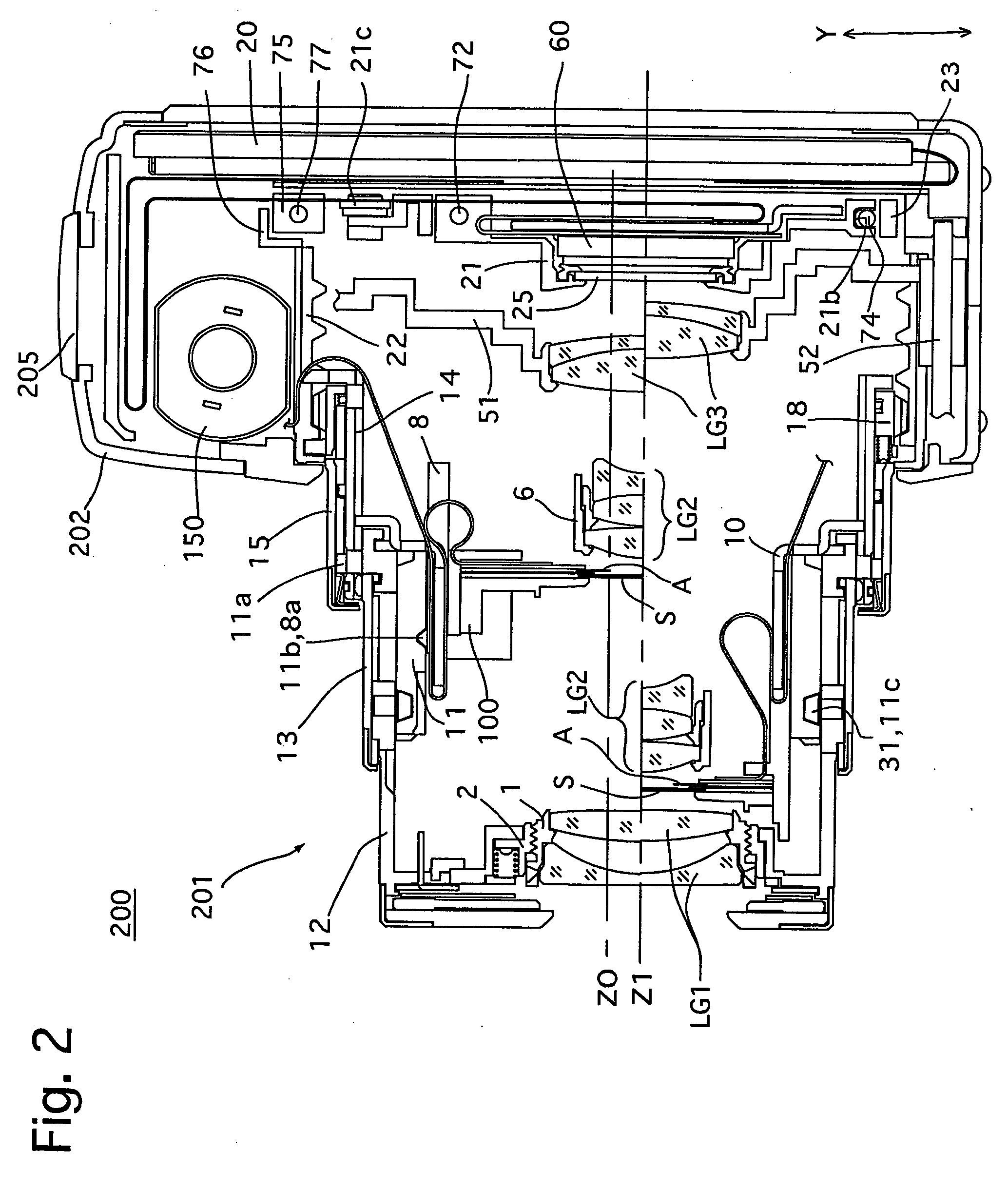
[0057] The zoom lens 201 of the digital camera 200, longitudinal sectional views of which are shown in FIGS. 2 and 3, is driven to advance toward the object side (leftward viewed in FIGS. 2 and 3) from the camera body 202 as shown in FIG. 2 during a photographing operation. When photography is no being carried out, the digital camera 200 moves from a ready-to-photograph state shown in FIG. 2 to a fully-retracted state shown in FIG. 3 in which the zoom lens 201 is accommodated (fully retracted) in the camera body 202 as shown in FIG. 3. In FIG. 2, the upper half and the lower half of the zoom lens 201 from a phot...


PUM


Abstract

An image stabilizer includes a guide device which guides an image-stabilizing optical element in a guide direction orthogonal to an optical axis and an image shake counteracting driving device which moves the image-stabilizing optical element so as to counteract image shake, including a first moving element moved by a drive source; a second moving element movable relative to the first moving element, and applies a moving force to a holder holding the image-stabilizing optical element when the second moving element is moved by the first moving element; and a moving-element control mechanism which resiliently connects the first and second moving elements to each other to allow the first and second moving elements to selectively move integrally and relative to each other in accordance with a magnitude of a resistance to a movement between the drive source and the holder.

Description

BACKGROUND OF THE INVENTION [0001] 1. Field of the Invention [0002] The present invention relates to an optical image stabilizer, incorporated in optical equipment such as a camera or binoculars, for counteracting image shake due to vibrations such as hand shake. [0003] 2. Description of the Related Art [0004] Image stabilizers (optical image stabilizers) for optical equipment prevent image shake from occurring on a focal plane by driving a part (image-stabilizing optical element) of an optical system relative to an optical axis thereof in accordance with the direction and the magnitude of vibration, such as hand shake, applied to the optical equipment. However, since the image-stabilizing optical element needs to be driven at high velocity in a fast responsive manner, such movement tends to be a burden on the driving mechanism therefor. Namely, the image-stabilizing optical element easily reaches a mechanical limit of movement thereof in the case where the magnitude of vibration is...

Claims


Application Information

Patent Timeline
IPC IPC(8): G03B17/00
CPCG03B5/02G03B17/04G03B2217/005G03B2205/0038H04N5/23248H04N5/23258H04N5/23287H04N5/2254H04N23/55H04N23/60H04N23/68H04N23/6812H04N23/687G02B27/646G03B5/00
Inventor NOMURA, HIROSHISUZUKA, SHINYAENDO, KEN
Owner HOYA CORP
Why Eureka
Try Eureka