Unlock instant, AI-driven research and patent intelligence for your innovation.

Advanced sintering process and tools for use in metal injection molding of large parts

a metal injection molding and advanced sintering technology, applied in metal-working apparatus, transportation and packaging, etc., can solve the problems of metal injection molding not being used to produce large parts, parts may sag under its own weight, soft and susceptible to deformation, etc., to achieve the effect of preventing deformation

Inactive Publication Date: 2007-01-04
HONEYWELL INT INC
View PDF14 Cites 23 Cited by
  • Summary
  • Abstract
  • Description
  • Claims
  • Application Information

AI Technical Summary

Benefits of technology

The present invention provides tool assemblies and methods for sintering a metal injection molded body. The tool assembly includes an insert and an endcap, which are designed to be inserted into the body's flowpath. The insert has a channel and a slot with an adjustable width, and the endcap is inserted into the channel at the insert's first end. The tool assembly helps to prevent deformation of the body's outer surface and ensures a smooth sintering process. The invention also provides a stand for supporting the body's side housing during sintering. The method involves disposing the insert assembly in the body's flowpath, sintering the body and insert assembly, and then removing the endcap and insert. The technical effects of the invention include improved sintering efficiency and reduced deformation of the body's outer surface.

Problems solved by technology

When the brown part is exposed to such temperatures, it may become soft and susceptible to deformation.
However, when large parts, e.g. parts larger than 250 grams, are subjected to sintering temperatures, portions of the part may sag under its own weight.
As a result, metal injection molding conventionally has not been used to produce large parts.

Method used


Image

  • Advanced sintering process and tools for use in metal injection molding of large parts
  • Advanced sintering process and tools for use in metal injection molding of large parts
  • Advanced sintering process and tools for use in metal injection molding of large parts

Examples


Embodiment Construction

[0020] The following detailed description of the invention is merely exemplary in nature and is not intended to limit the invention or the application and uses of the invention. Furthermore, there is no intention to be bound by any theory presented in the preceding background of the invention or the following detailed description of the invention. Additionally, although the apparatus are depicted as primarily being used in conjunction with a brown body, it will be appreciated that the apparatus may be employed with green bodies or other flowbodies having at least one flowpath formed therein.

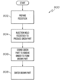
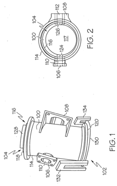
[0021]FIGS. 1 and 2 illustrate a brown body 100 and an exemplary tool assembly 102 positioned therearound before a sintering process. It will be appreciated that the brown body 100 shrinks a predetermined amount after being exposed to the sintering process. Thus, as illustrated in FIG. 1, the brown body 100, in relation to the tool assembly 102, is a percentage larger in size than the tool assem...


PUM

PropertyMeasurementUnit
temperaturesaaaaaaaaaa
weightaaaaaaaaaa

Abstract

Tools and methods are provided for use in a process for sintering a metal injection molded body where the body comprises a material and having a first end, a second end, and a flowpath extending therebetween, the flowpath having a diameter. The tool assembly comprises an insert and an endcap. The insert is configured to be disposed in the body flowpath and has an inner surface, an outer surface, a first end, a second end, a channel, a slot having a width, an inner diameter and an outer diameter. The endcap is configured to be inserted at least partially into the channel at the insert first end when the slot width is increased, and at least a portion of the endcap has an outer diameter that is substantially equal to or larger than the insert inner diameter.

Description

TECHNICAL FIELD [0001] The present invention relates to metal injection molding of parts weighing over 250 grams and, more particularly, to methods and tools for use in metal injection molding. BACKGROUND [0002] Metal injection molding is a simple, cost-effective method that has widely been used to mold parts weighing less than 250 grams. This process has been used to inexpensively manufacture a myriad of components used in many different industries, such as automotive, firearms, and medical industries. Generally, metal injection molding includes four basic steps, namely, mixing fine metal powders with a binder to formulate a feedstock, molding the feedstock in an injection molding machine to form a green part, debinding the binder from the green part to produce a brown part, and sintering the brown part to form the component. [0003] During sintering, the brown part is subjected to temperatures of at least about 2200° F. and may be as high as about 2800° F. for some iron-based alloy...

Claims


Application Information

Patent Timeline
Patent Type & Authority Applications(United States)
IPC IPC(8): B22F3/10
CPCB22F3/1017B22F2998/10B22F1/0059B22F3/225B22F3/1021B22F3/10
Inventor LU, JYH-WOEI J.BYE, RICHARD L.TERVO, JOHN N.LASALLE, JERRY C.
Owner HONEYWELL INT INC