
Soap dispenser extruding device

a dispenser and extruder technology, applied in the direction of liquid/fluent solid measurement, volume metering, instruments, etc., can solve the problems of hard pressing operation activation, limiting the quantity and stability of liquid, and the working performance is not as expected, so as to achieve accurate control of soap liquid outlet and energy saving operation

Inactive Publication Date: 2007-01-11
LIN YENG TANG
View PDF7 Cites 14 Cited by
  • Summary
  • Abstract
  • Description
  • Claims
  • Application Information

AI Technical Summary

Benefits of technology

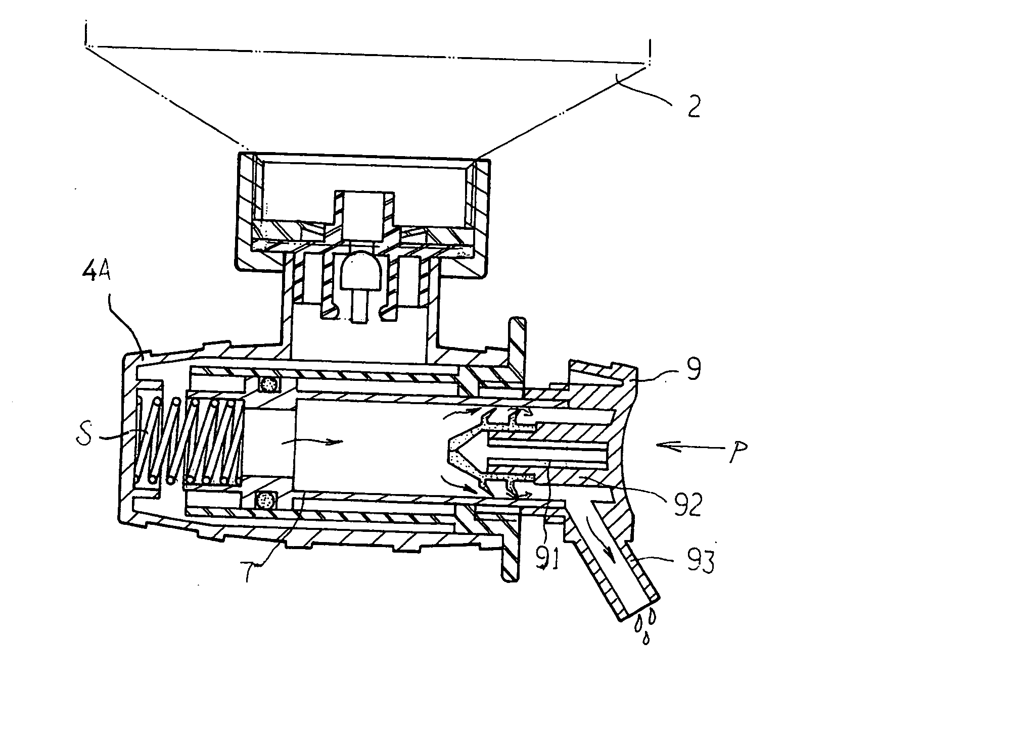
[0007] The primary purpose of the present invention is to provide an extruding device for soap liquid outlet, whether the fluid in the soap dispenser is light or heavy, the position of the outlet of a soap dispenser could be set up in any direction due because of the control of the fluid leading course and the distribution of the operating zone, wherein the outlet of the soap dispenser is bolted on an inner partition plate with a nut. In the center of this plate is installed a containing ball seat, and this plate is fixed on the fluid inlet side of a containing tube body, then under the fluid inlet side of the containing tube body forms a cross containing space, and surrounding this containing space there are holes with screw thread for fluid outlet fitting, a checking valve is installed, a soap liquid feeding header with an outlet tube is screwed into the hole with its inner thread. The features are: a piston bush which is fixed in the containing space of containing tube body, for forming twin tube body set, there is a piston rod in piston bush, one end of piston rod is connected with a spring, and other end of the piston rod is fixed with a sealing lid. This sealing lid should match the shaft hole on the piston bush and once the running position of sealing lid to the shaft hole on piston bush has been fixed, this sealing lid could have a free displacement due spring force. Therefore the position of feeding direction of soap liquid is not limited and energy saving for operation is achieved and also accurate control of soap liquid outlet and stoppage of liquid after service are emerged.
[0010] Another object of the present invention is to provide an extruding device for soap dispenser, with such a design that the soap liquid wouldn't be overflowed from the hollow part of piston rod at standby service condition due the closing fitting ring between piston rod and containing space.

Problems solved by technology

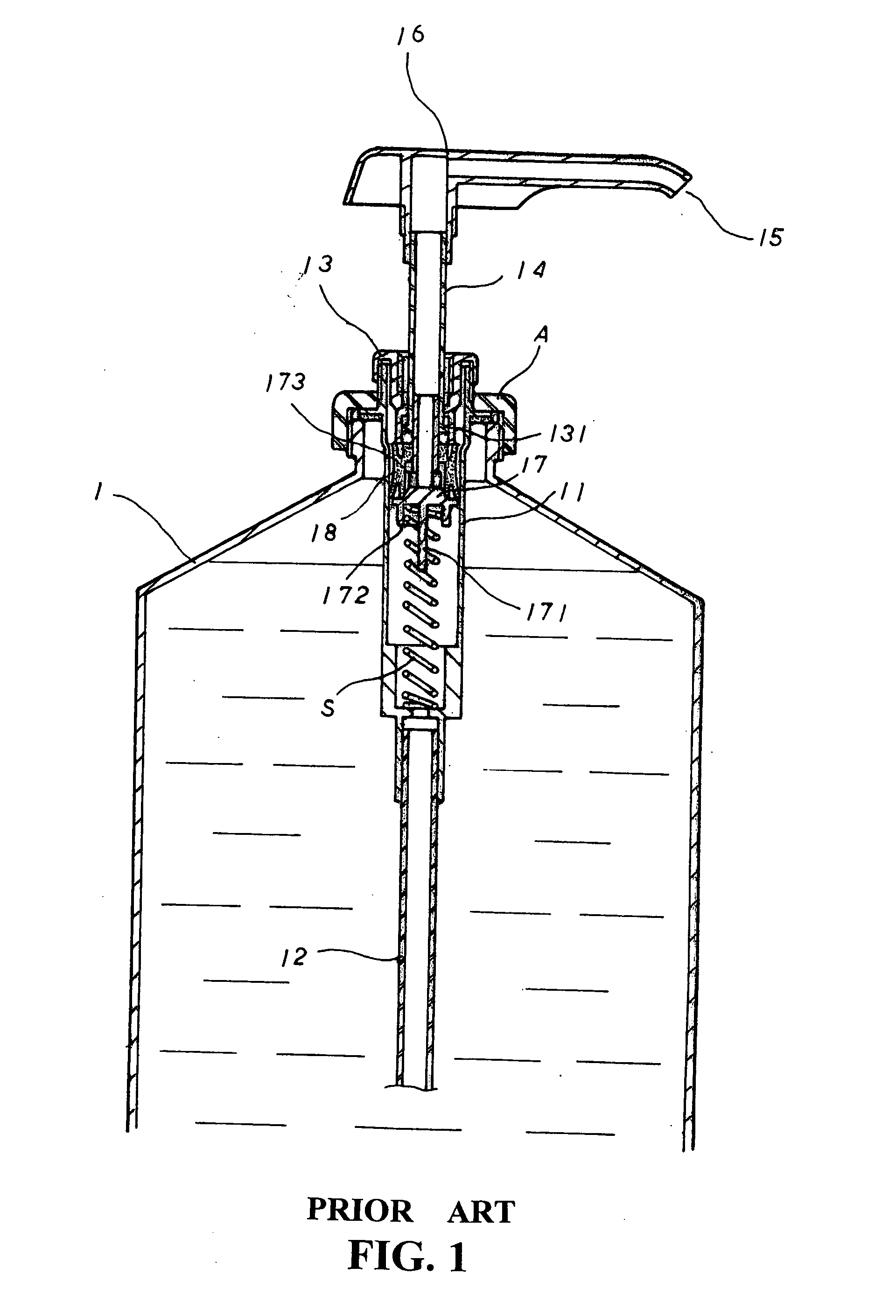
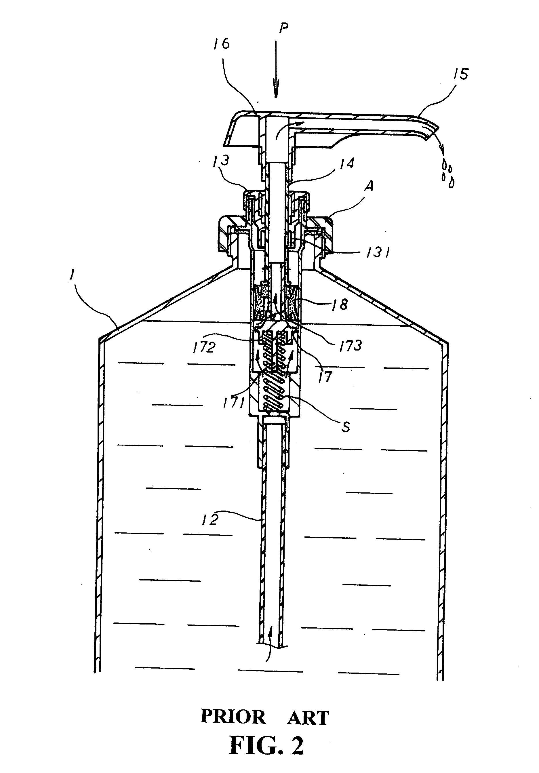
But this pressing operation activation is hard because of resistance due to the improper design of the shaft rod and shaft ring.
However the alignment problem of central passage hole 35 to shaft ring hole 43 would limit the liquid flow quantity and stability.
Therefore its working performance isn't as expected.
The liquid in the container tube would cause resistance of the movement of hollow piston 30 which makes the operation difficult.
Nevertheless, its service function depends upon the matching of the mechanism manipulation to the standard liquid outlet and inlet directions, so its structure formation and service possibilities are limited.
I believe that everybody has had this inconvenient experience before.

Method used


Image

  • Soap dispenser extruding device
  • Soap dispenser extruding device
  • Soap dispenser extruding device

Examples


Embodiment Construction

[0024] The following descriptions are of exemplary embodiments only, and are not intended to limit the scope, applicability or configuration of the invention in any way. Rather, the following description provides a convenient illustration for implementing exemplary embodiments of the invention. Various changes to the described embodiments may be made in the function and arrangement of the elements described without departing from the scope of the invention as set forth in the appended claims.

[0025] Please refer to the FIGS. 1, 2 and 3, the features of this invention are; the outlet end 21 of soap dispenser container 2 is screwed with in a shim 3 by nut A, there is a ball valve R's seat 31 in the central of shim 3, this shim 3 shall be fixed in the liquid inlet end 42 of a containing tube body 4, there is a thread outlet end 43 on containing tube body for connecting the soap liquid feeder 5 with outlet 51 by screwing on, there is a plunger with groove 521 above outlet 51 in soap liq...


PUM


Abstract

A soap dispenser extruding device that decrease operation resistance, release the restriction of liquid outlet orientation, increase the working efficiency of a soap dispenser and product cost saving are the key points, besides there are also functions of non soap liquid to be overflow before soap dispenser in service or no any soap liquid residues to be left after soap dispenser in service. A piston rod is moving back and forth against a spring in piston bush, activating a ball checking valve for controlling of flowing soap liquid from soap liquid container to piston bush. Another checking valve located in the end of the hollow part of piston rod is for controlling flowing of soap fluid from piston bush to liquid outlet. When piston rod is pushing in, this is soap dispenser in service; when piston is spring back; a suction force is absorbing residue in outlet; this is soap dispenser out of service.

Description

BACKGROUND OF THE INVENTION [0001] (a) Field of the Invention [0002] The present invention is related to a soap dispenser extruding device. Such invention make possible the installing of the piston rod and piston bush of the extruding device in the space of container, and separating the operating system from soap liquid feeding system. Therefore the operating resistance and the limitation of soap liquid outlet position could be decreased. Such effects would result in increase soap dispenser efficiency, energy saving for operation, and the economical effect of product cost deduction for assembling a soap dispenser on line. [0003] (b) Description of the Prior Art [0004] There are two different functions of the soap dispenser to be sold in current market, one is the wall adhering type and the other is the vertical type. The liquid soap container of wall adhering type is in the up and down position. The soap liquid extrudes out by a horizontal pressing operation. But this pressing opera...

Claims


Application Information

Patent Timeline
IPC IPC(8): B65D88/54G01F11/00
CPCG01F11/025A47K5/1207
Inventor LIN, YENG-TANG
Owner LIN YENG TANG
Learn More