Brush holding device

a technology of dc motor and holding device, which is applied in the direction of current collectors, dynamo-electric machines, electrical apparatus, etc., can solve the problems of difficulty in engaging pieces, difficulty in having a sufficiently high strength of the brush holding device b>100/b>, and insufficient height, so as to prevent the load necessary, large fixing force, and large strength

Active Publication Date: 2007-01-11
DENSO CORP
View PDF7 Cites 40 Cited by
  • Summary
  • Abstract
  • Description
  • Claims
  • Application Information

AI Technical Summary

Benefits of technology

[0014] According to the present invention, in which the bridge portions on the both lateral sides of the opening portion are inserted into the fitting grooves formed in the both lateral sides of the thick-wall portion, so that the thick-wall portion is caught in the width direction thereof between the bridge portions, it is possible for the brush holder to receive a fixing force at the thick-wall portion thereof. Accordingly, with the present invention, it is possible to provide the brush holder with a sufficiently large strength to withstand

Problems solved by technology

The above described brush holding device has a problem in that it is difficult for the engaging pieces 111 have a sufficient height, because they are formed by partially cutting out the surface of the holder plate 110.
This makes it difficult for the brush holding

Method used


Image

  • Brush holding device
  • Brush holding device
  • Brush holding device

Examples


first embodiment

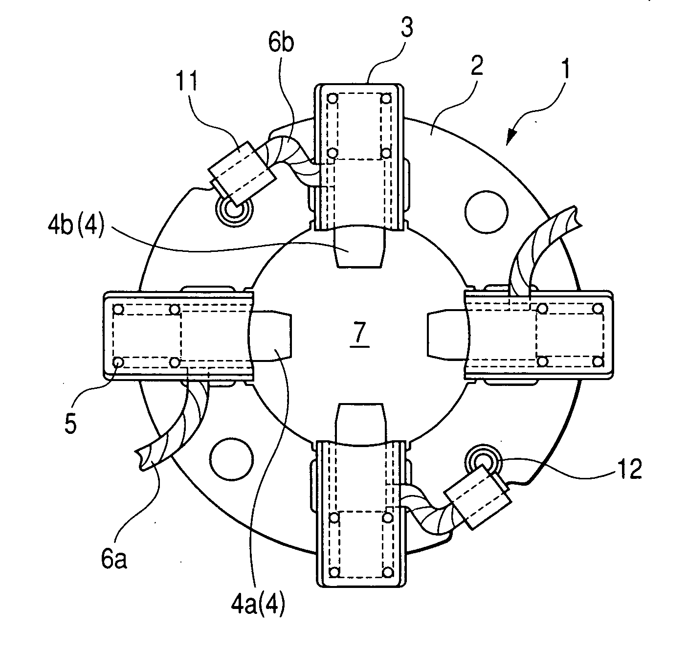
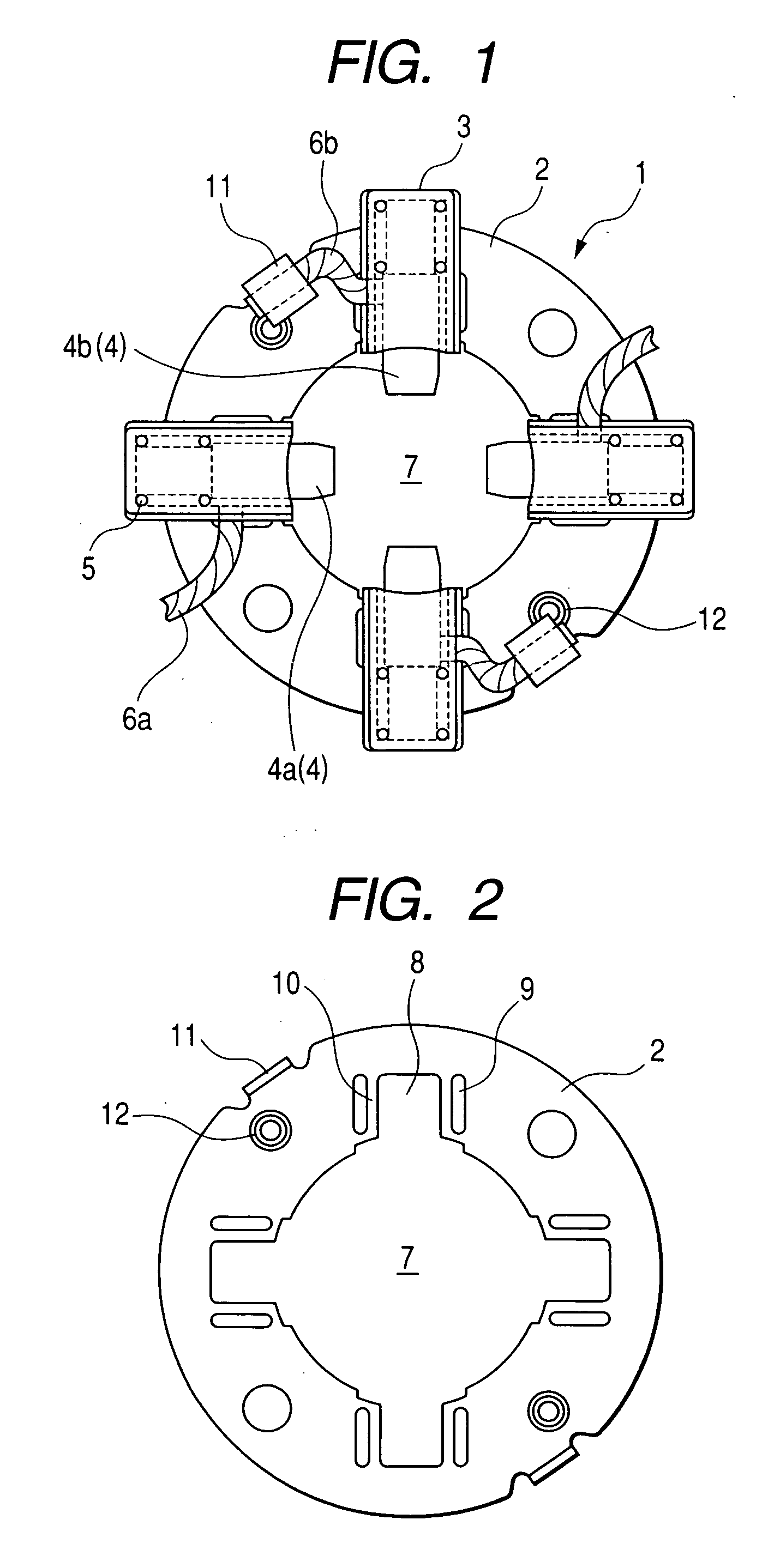
[0026] Fig. is a plan view of a brush holding device 1 according to a first embodiment of the invention. The brush holding device 1, which can be used for an engine starter of a vehicle, for example, includes a holder plate 2 made of a thin metal plate such as a steel plate, and resin-made brush holders 3 fitted to the holder plate 2. Brushes 4 held in the brush holders 3 are disposed around a commutator (not shown) of an armature (not shown).

[0027] The brush 4 includes two positive brush members 4a and two negative brush members 4b disposed respectively at the positive electrode side and at the negative electrode side of the armature. These brush members are biased towards the commutator by a brush spring 5. Each of the positive brush members 4a is connected to a field coil (not shown) through a lead wire 6a. Each of the negative brush members 4b is connected to the holder plate 2 through a lead wire 6b.

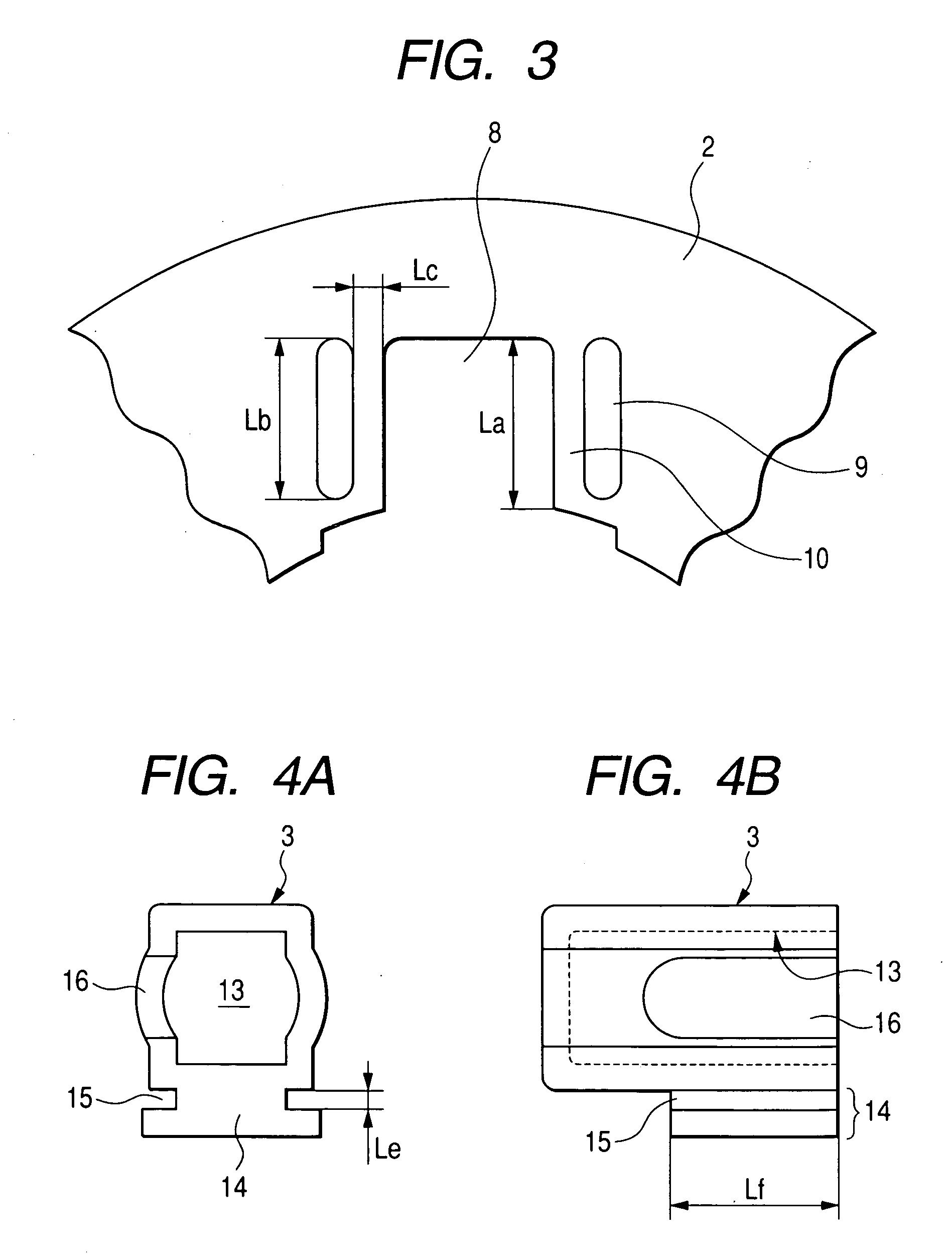
[0028] As shown in FIG. 2, the holder plate 2 has a circular outer shape, and...

second embodiment

[0036]FIG. 6 is a partially enlarged view of the holder plate 2 of a brush holding device according to a second embodiment of the invention, which shows the opening portion 8 and its vicinity.

[0037] As shown in this figure, in the second embodiment, projecting portions 17 are formed in the both lateral sides of the opening portion 8 of the holder plate 2 such that they project towards each other. The projecting portion 17 is situated midway of the lateral side of the opening portion 8, and has a projection height g smaller than the thickness Ld of the holder plate 2 (see FIG. 5). In this embodiment, the degree of yielding of the bridge portion 10 at the middle portion thereof when the bridge portion 10 is inserted into the fitting groove 15 is larger than those at the end portions thereof because of the provision of the projecting portion 17. Accordingly, in this embodiment, the brush holder 3 can be held firmly by the projecting portion 17 and the end portions of the opening porti...


PUM


Abstract

The brush holding device includes a brush holder having a brush-housing chamber, and a holder plate to which the brush holder is attached. The holder plate is formed with a center hole at a center portion thereof, the center hole having a size allowing a commutator to path therethrough, and a pair of elongated holes opposing to each other with respect to the opening portion, the elongated holes defining bridge portions with the opening hole. The brush holder has a thick-wall portion integral with a bottom wall of the brush-housing chamber, the thick-wall portion being formed with fitting grooves at lateral sides thereof. The bridge portions are inserted into the fitting grooves so that the brush holder is fitted to the holding plate in such a state that the thick-wall portion is caught between the bridge portions.

Description

CROSS-REFERENCE TO RELATED APPLICATION [0001] This application is related to Japanese Patent Application No. 2005-200589 filed on Jul. 8, 2005, the contents of which are hereby incorporated by reference. BACKGROUND OF THE INVENTION [0002] 1. Field of the Invention [0003] The present invention relates to a brush holding device of a DC motor. [0004] 2. Description of Related Art [0005] A DC motor having a brush is provided with a brush holding device as described in, for example, in Japanese Patent No. 3486094. As shown in FIG. 7, this brush holding device is constituted by a brush holder 100 made of resin for housing a brush (not shown), and a holder plate 110 to which the brush holder 100 is fixed. The holder plate 110 has a pair of engaging pieces 111 which are partially cut out from the surface thereof, and are bent so as to oppose to each other. The brush holder 100 is provided with, at a bottom part thereof, plate-like convex parts 101 projecting laterally. These plate-like conv...

Claims


Application Information

Patent Timeline
IPC IPC(8): H01R39/38
CPCH01R39/385
Inventor NIIMI, MASAMI
Owner DENSO CORP
Why Eureka
Try Eureka