
Method for determining camera position from two-dimensional images that form a panorama

Inactive Publication Date: 2007-01-11
SEIKO EPSON CORP
View PDF15 Cites 105 Cited by
  • Summary
  • Abstract
  • Description
  • Claims
  • Application Information

AI Technical Summary

Benefits of technology

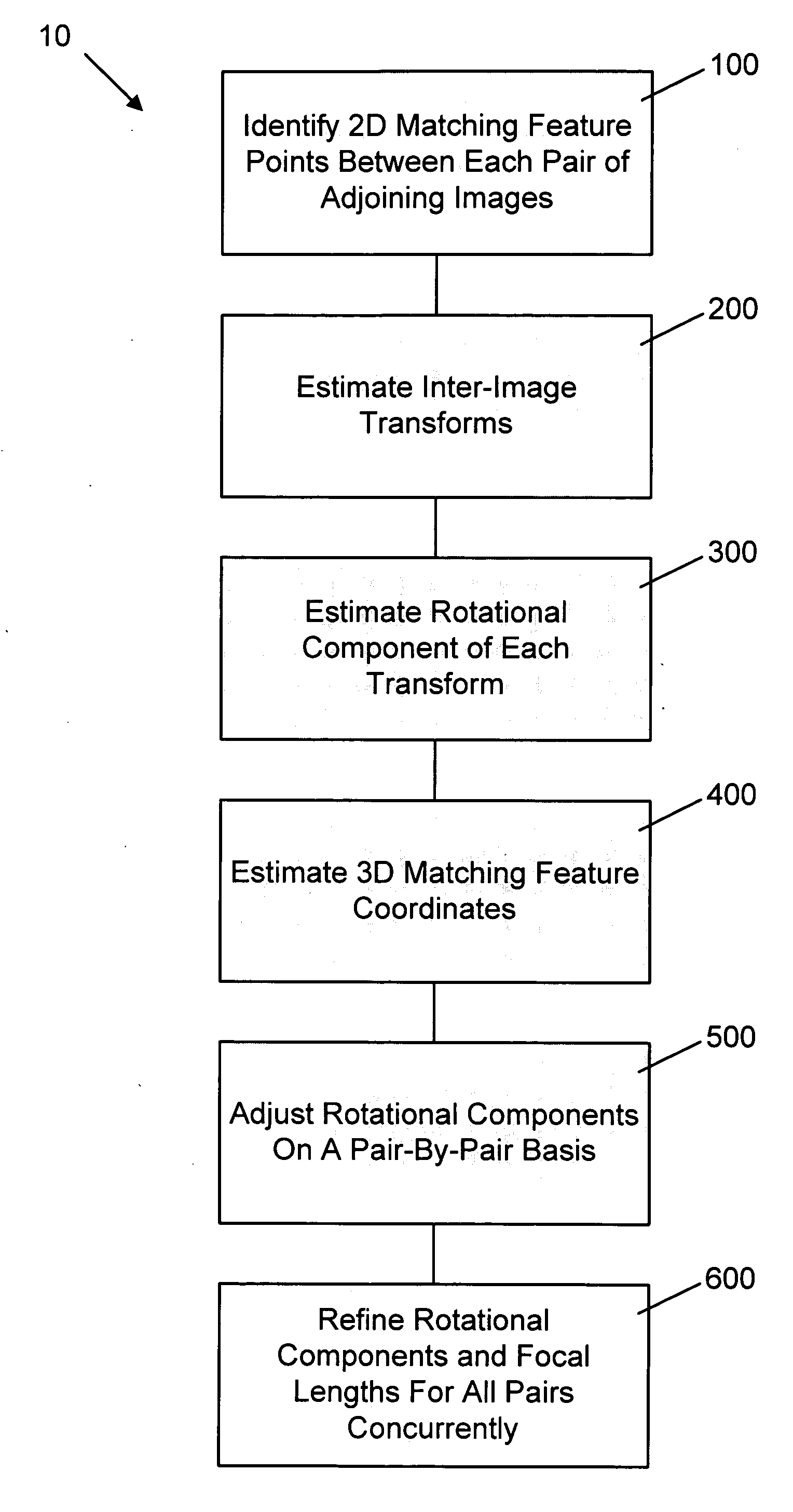
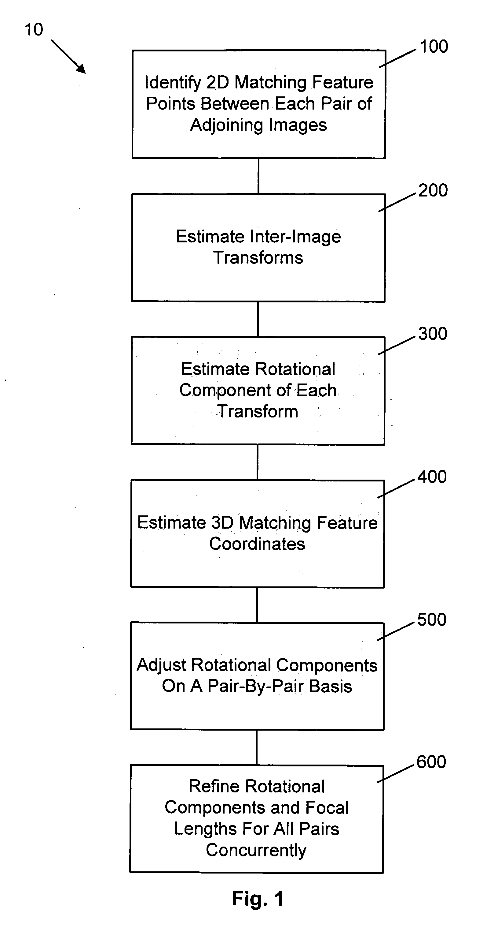
[0012] adjusting each of the rotational components to reduce errors between corresponding ones of said coordinates in adjoining image pairs; and
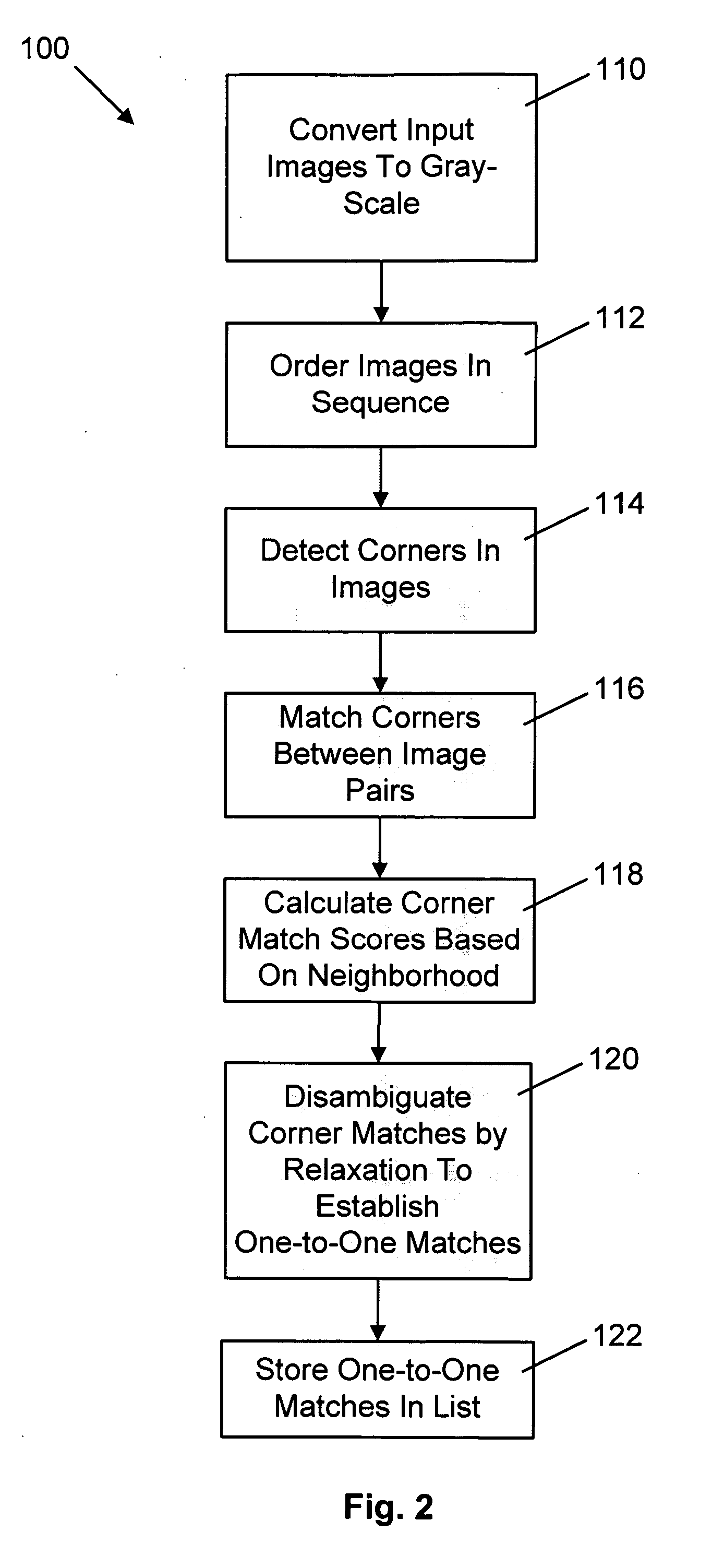
[0014] In one embodiment, the common features are matching corners. The rotational component is determined by making an initial estimate of the focal length for each image. This may be done by calculating the diagonal of the image as the focal length. Prior to the adjusting, a reference image is placed onto an equator of a three-dimensional model, at a distance equal to a respective initial estimate of focal length from an origin of the model. Adjoining images are sequentially placed into the model based on respective initial estimates of focal length and rotational component and rays are identified from the origin to corresponding ones of the coordinates in adjoining images. Adjusting thereby comprises reducing error in direction between corresponding ones of the rays.
[0020] adjusting each rotational component to reduce differences between said common features in a three-dimensional coordinate system; and
[0025] an adjustor adjusting each of the rotational components to reduce errors between corresponding ones of said coordinates in adjoining image pairs; and
[0031] means for adjusting each rotational component to reduce differences between said common features in a three-dimensional coordinate system; and
[0044] Because common features such as matching corners are used to estimate a transform between adjoining images, the identified common features are already available to be used for adjusting the rotational components. Use of these common features during the rotational component adjustment stage saves additional processing resources and time. Furthermore, because a gradient-based optimization technique for directly estimating the 3D rotation matrix and focal lengths is not employed, slow convergence and getting stuck in local minima is avoided. These problems are common when using gradient based optimization with eight- or even three-parameter rotational models. Employing common feature points built up during registration allows linear equations to be directly solved and as a result the camera position from a set of two-dimensional images that form a panorama can be estimated in a simple manner that requires fewer steps than the prior art techniques described above.

Problems solved by technology

In many instances, it is difficult or impossible for a photographer to capture a desired entire scene within a digital image and retain the desired quality and zoom.
Simple image stitching in this instance is not possible because some of the images will have been captured behind the chosen point of view of the two-dimensional image.
However, such three-dimensional information is lost when a single image is captured in two-dimensions.

Method used


Image

  • Method for determining camera position from two-dimensional images that form a panorama
  • Method for determining camera position from two-dimensional images that form a panorama
  • Method for determining camera position from two-dimensional images that form a panorama

Examples


Embodiment Construction

[0053] In the following description, embodiments of a method, apparatus and computer program for estimating camera position information from a series of source images that form a panorama are provided. During camera position estimation, a transform between adjoining image pairs in the series based on common features within the adjoining image pairs is estimated. A rotational component for each transform and three-dimensional coordinates for the common features are determined. Each of the rotational components is adjusted to reduce errors between corresponding ones of the coordinates in adjoining image pairs. Focal lengths are then calculated based on the adjusted rotational components.

[0054] The method and apparatus may be embodied in a software application including computer executable instructions executed by a processing unit such as a personal computer or other computing system environment. The software application may run as a stand-alone digital image editing tool or may be i...


PUM


Abstract

A method of estimating three-dimensional camera position information from a series of two-dimensional images that form a panorama employs common features in adjoining image pairs in the series to estimate a transform between the images in the pairs. The common features are subsequently employed to adjust an estimated rotational component of each transform by reducing error between coordinates corresponding to the common features in three-dimensional space in image pairs, on a pair-by-pair basis. A global optimization of the position estimation, used for long sequences of images such as 360 degree panoramas, refines the estimates of the rotational and focal length components of the transforms by concurrently reducing error between all 3D common feature coordinates for all adjoining pairs.

Description

FIELD OF THE INVENTION [0001] The present invention relates generally to image processing and more particularly to a method, apparatus and computer program for estimating three-dimensional camera position information from a plurality of two-dimensional source images that combine to form a panorama. BACKGROUND OF THE INVENTION [0002] Digital cameras are becoming increasingly popular and as a result, a demand for image processing software that allows photographers to edit digital images exists. In many instances, it is difficult or impossible for a photographer to capture a desired entire scene within a digital image and retain the desired quality and zoom. As a result, photographers are often required to take a series of overlapping images of a scene and then stitch the overlapping images together to form a panorama. [0003] Many techniques for creating a panorama from a series of overlapping images have been considered. For example, U.S. Pat. No. 6,549,651 to Xiong et al. discloses a...

Claims


Application Information

Patent Timeline
IPC IPC(8): G06T15/00
CPCG06T7/0018G06T2207/10012G06T2200/32G06T7/80
Inventor ZHOU, HUIKWOK, DEREK HANG CHUNCLARKE, IAN
Owner SEIKO EPSON CORP
Learn More