
Image combining system, image combining method, and program

Active Publication Date: 2007-01-11
NEC CORP
View PDF7 Cites 32 Cited by
  • Summary
  • Abstract
  • Description
  • Claims
  • Application Information

AI Technical Summary

Benefits of technology

[0014] It is therefore an object of the present invention to provide an image combining system and method which are capable of generating a mosaic image through simple operations without the need for complicated and subtle operations such as manipulations of a switch, parallel movements of a camera, alignment between partial images, and the like by the user.
[0016] In such a configuration, the user is not required to previously specify, with a switch, a direction in which a camera is moved, or to move the camera in parallel with an imaging plane, or to adjust a camera panning to avoid a discontinuous image at the boundary of a current partial image with a photographed partial image, as required in a conventional image combining system. Consequently, a mosaic image can be generated even for a subject which is broad in the vertical and horizontal directions, through simple manipulation, without the need for complicated manipulations or alignment by the user.
[0017] Also, in the present invention, each image conversion parameter is optimized so as to maintain the consistency of the geometric conversion and combination among all partial images. Accordingly, shifts in the combination are eliminated between partial images which were photographed at separate times, thus achieving a mosaic image with less distortion. Further, the mosaic image can be generated at a higher resolution by applying super resolution processing to each partial image.
[0019] As a result, since not only the current partial image but also at least part of the mosaic image are displayed on the display device, the user can readily confirm an area of the subject which has not been photographed, and can readily determine in which direction the camera should be next moved. Therefore, even when photographing a subject which is broad in the vertical and horizontal directions, the user will not forget to photograph part of the subject.

Problems solved by technology

Otherwise, no corresponding points would exist between the partial images, resulting in a failure in calculating the image conversion parameters.
Also, if part of the subject is not photographed when the partial images are photographed, a mosaic image lacks the partial images, so that a user must exhaustively photograph the subject.
Since a direction in which the camera is moved must be previously specified by the switch, a problem arises in that the operation is very complicated.
Thus, the user is required to perform subtle operations, causing a problem that the user experience considerable difficulty taking photographs.

Method used


Image

  • Image combining system, image combining method, and program
  • Image combining system, image combining method, and program
  • Image combining system, image combining method, and program

Examples


first embodiment

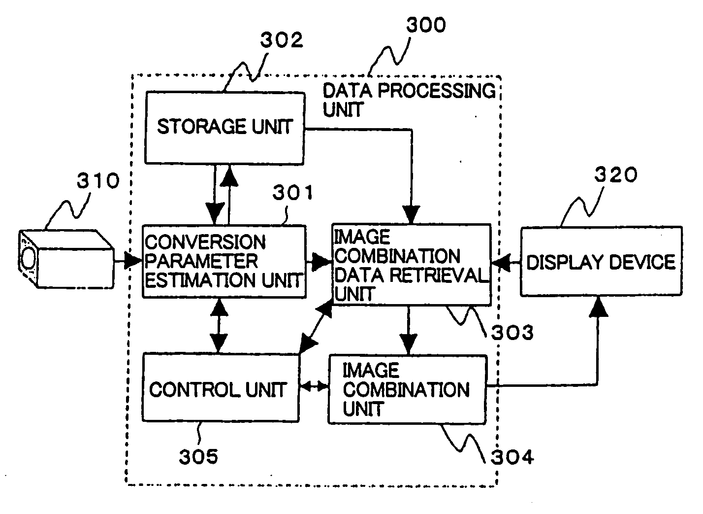
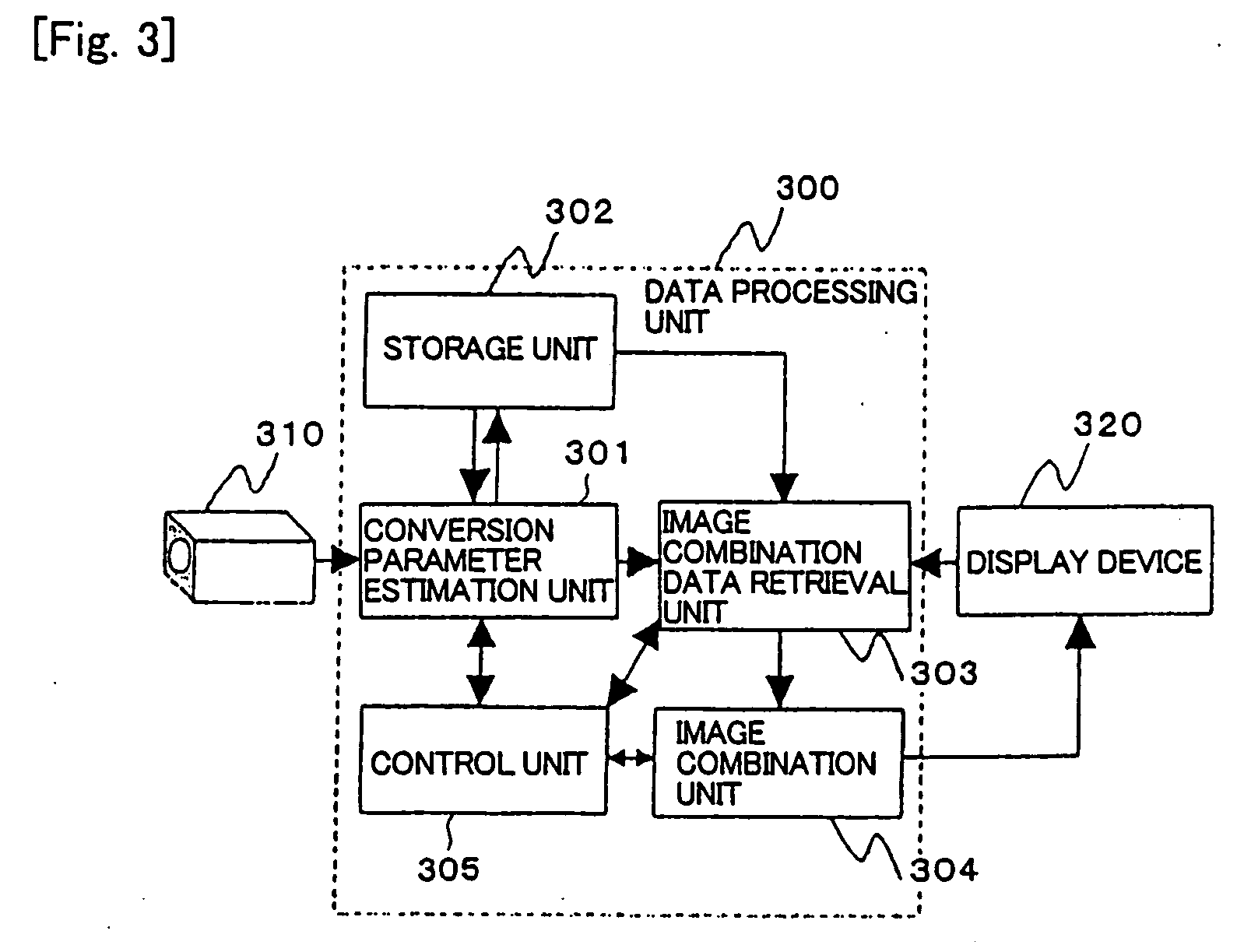
[0033] As illustrated in FIG. 3, an image combining system of a first embodiment comprises imager device 310 such as a still camera, a video camera or the like; data processing unit 300 for combining partial images to generate a mosaic image; and display device 320 such as a liquid crystal panel, a Braun tube or the like for displaying the result of processing by data processing unit 300. Data processing unit 300 is implemented by an LSI (Large scale Integrated Circuit), a logic circuit or the like which comprises a calculation function and a memory.

[0034] Data processing unit 300 in the first embodiment comprises conversion parameter estimation unit 301, storage unit 302, image combination data retrieval unit 303, image combination unit 304, and control unit 305.

[0035] Conversion parameter estimation unit 301 estimates the geometric conversion required for a combination of a previously photographed (preceding) partial image, among partial images photographed by imager device 310,...

second embodiment

[0065] Next, a second embodiment of the image combining system of the present invention will be described using the drawings.

[0066] As illustrated in FIG. 8, the image combining system of the second embodiment, like the first embodiment, comprises imager device 510 such as a still camera, a video camera or the like; data processing unit 500 for combining partial images to generate a mosaic image; and display device 520 such as a liquid crystal panel, a Braun tube or the like for displaying the result of processing by data processing unit 500. Data processing unit 500 is implemented, for example, by an LSI, a logic circuit or the like which comprises a calculation function and a memory.

[0067] Data processing unit 500 in the second embodiment comprises mosaic image generation unit 501, and overall optimization unit 502.

[0068] Mosaic image generation unit 501 comprises functions similar to those of data processing unit 300 in the first embodiment, and geometrically converts and comb...

third embodiment

[0085] Next, a third embodiment of the image combining system of the present invention will be described using the drawings.

[0086] As illustrated in FIG. 10, the image combining system of the third embodiment, like the first embodiment, comprises imager device 710 such as a still camera, a video camera or the like; data processing unit 700 for combining partial images to generate a mosaic image; and display device 720 such as a liquid crystal panel, a Braun tube or the like for displaying the result of processing by data processing unit 700. Data processing unit 700 is implemented, for example, by an LSI, a logic circuit or the like which comprises a calculation function and a memory.

[0087] Data processing unit 700 of the third embodiment comprises mosaic image generation unit 701, and super resolution image generation unit 702.

[0088] Mosaic image generation unit 701, which comprises similar functions as those of data processing unit 300 in the first embodiment or data processing...


PUM


Abstract

A data processing device calculates an image conversion parameter corresponding to each partial image. According to the image conversion parameter calculated, a partial image which has been imaged according to the current partial image is geometrically converted. The images are combined to generate a mosaic image. Moreover, the current partial image and at least a part of the mosaic image generated are displayed on a display unit.

Description

TECHNICAL FIELD [0001] The present invention relates to an image combining system, an image combining method, and an image combination program for dividing a subject into a plurality of partial images, photographing the divided partial images, and combining these partial images to generate an image having a wider viewing angle and a higher definition. BACKGROUND ART [0002] Conventionally, image combining approaches have been known for dividing a subject into a plurality of partial images which are photographed, and combining the partial images with one another with estimation of a positional relationship among the respective partial images to generate an image called a mosaic image which has a wider viewing angle and a higher definition. [0003] For example, Non-Patent Document 1 (Naoki Chiba, Hiroshi Kayano, Mitihiko Mino, Shouji Yasuda, “Image Mosaicking Based on Image Features,” Transaction of The Institute of Electronics, Information and Communication Engineers D-II, Vol. J82-D-I...

Claims


Application Information

Patent Timeline
IPC IPC(8): G03B21/14G06T3/00H04N1/387
CPCH04N1/3876G06T3/4038
Inventor IKETANI, AKIHIKONAKAJIMA, NOBORUSATO, TOMOKAZUIKEDA, SEIKANBARA, MASAYUKIYOKOYA, NAOKAZU
Owner NEC CORP
Learn More