Voltage regulator converter without switching losses

a voltage regulator and converter technology, applied in the field of electric supplies, can solve the problems of reducing converter performance and only applying solutions, and achieve the effect of reducing footprint and mass

Inactive Publication Date: 2007-01-11
EUROPEAN SPACE AGENCY
View PDF11 Cites 18 Cited by
  • Summary
  • Abstract
  • Description
  • Claims
  • Application Information

AI Technical Summary

Benefits of technology

[0007] The invention is designed to resolve one or several of these disadvantages. A complementary objective of the invention is to provide such a converter which can respond to constraints imposed by satellite systems, namely sound operational reliability (through minimization of the number of components, and simplicity of redundancy) and a minimal footprint and mass. A complementary objective of the invention is to provide such a converter adapted to operate at very high switching frequency or very high output voltage value.

Problems solved by technology

This converter presents disadvantages: transistors Q1 and Q2 switch when the current that crosses them is non zero and the opening of these transistors takes place when their drain-source voltage is non zero, causing a decrease in the converter performance.
In addition, this solution only applies for a square wave push-pull converter.

Method used


Image

  • Voltage regulator converter without switching losses
  • Voltage regulator converter without switching losses
  • Voltage regulator converter without switching losses

Examples


Embodiment Construction

)

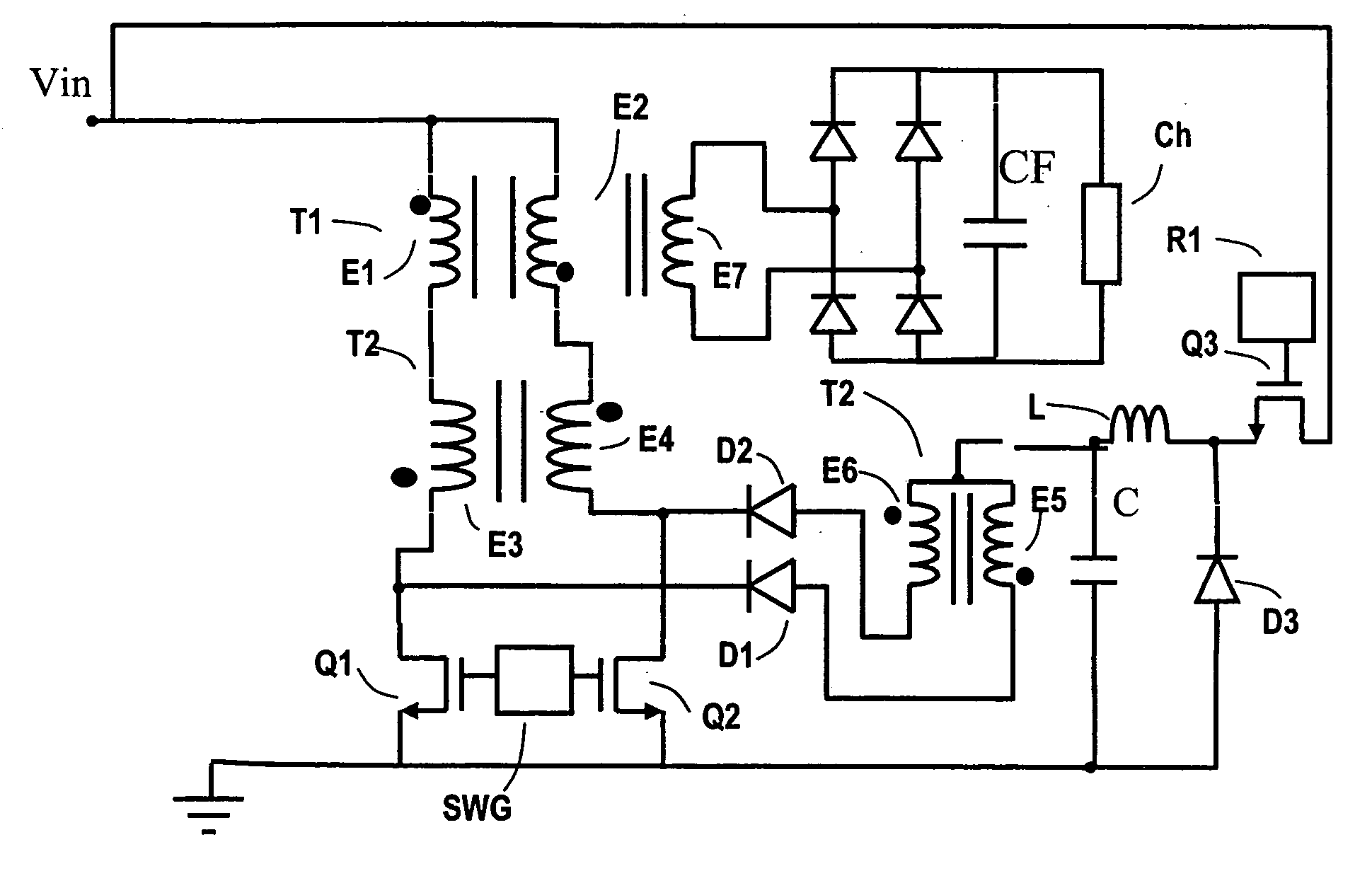
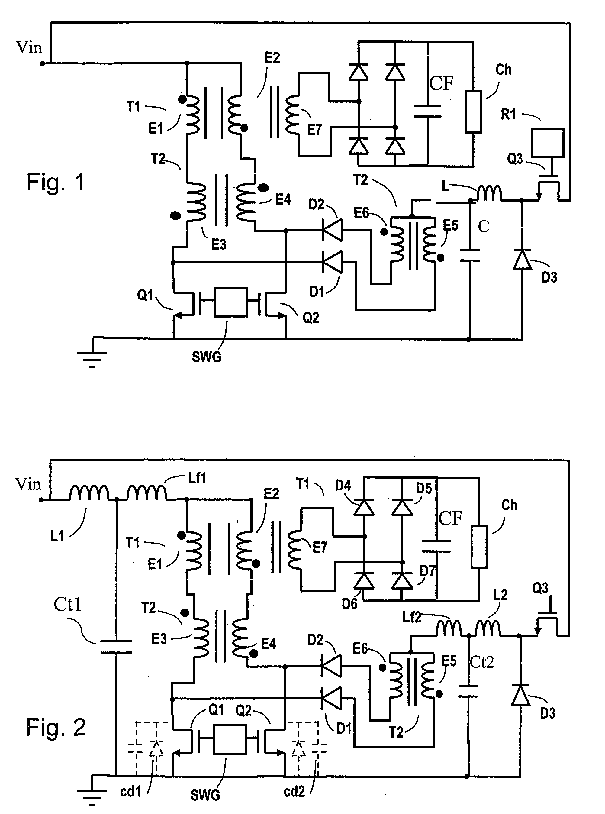
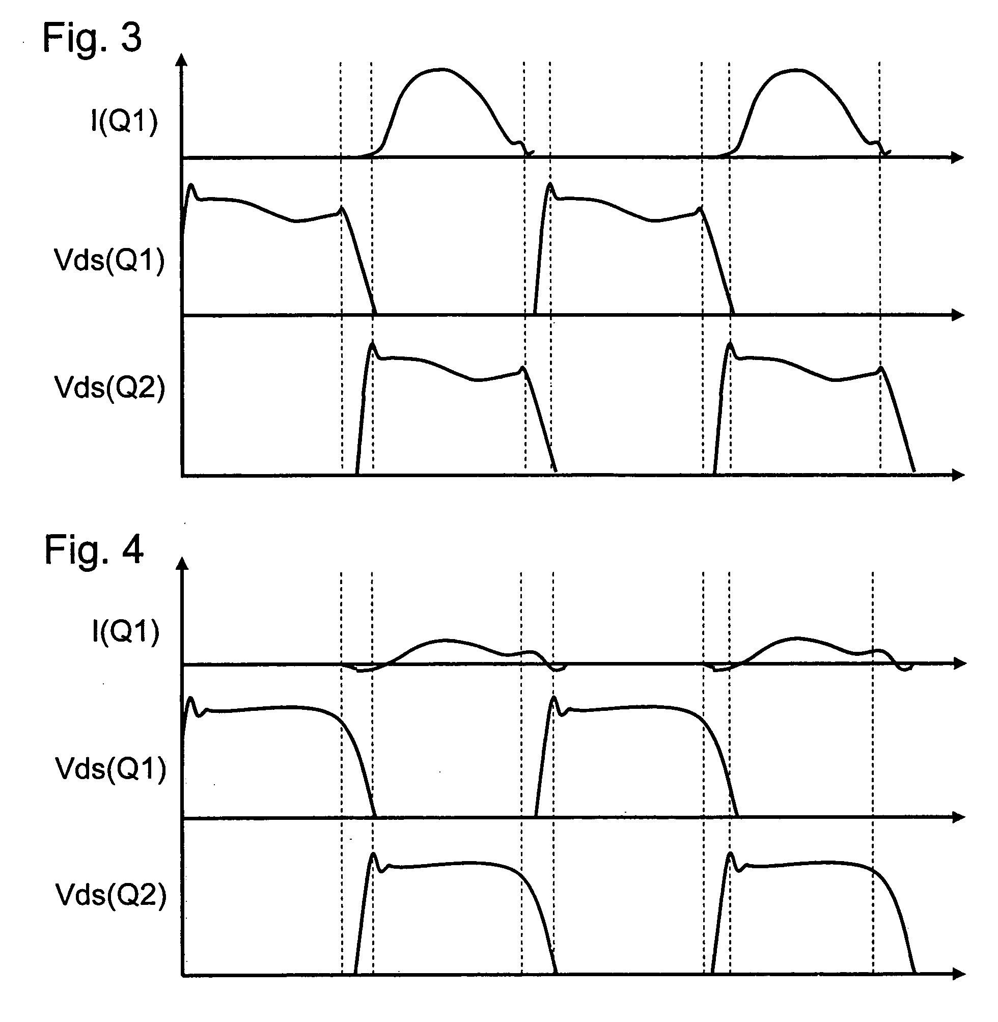
[0036] The invention proposes a converter provided with a main transformer and a regulation transformer. The regulation transformer presents a secondary winding placed in series with a winding of the main transformer. A winding of the primary winding of the main transformer is placed in a first resonant circuit whose opening and closing are controlled by a switching device. A winding of the primary winding of the regulation transformer is placed in a second resonant circuit whose opening and closing are controlled by the switching device. The resonance frequencies of the first and second circuits are at least equal to the opening or closing frequencies of the switching device. The switching of the switching device thus takes place at zero current. Advantageously, the resonance frequencies of the first and second resonant circuits are substantially identical, so that the shape of the current crossing the switching device is substantially identical and so the switching at zero curren...


PUM


Abstract

The invention concerns a converter which includes two input terminals and two output terminals, a main transformer presenting primary and secondary windings connected between the input terminals and the output terminals respectively, a switching device, a first inductance and a first capacitance forming a first resonant circuit with the primary winding of the main transformer, a wound regulation transformer, presenting a primary winding, and a secondary winding connected in series with one of the windings of the main transformer, a switching device, a second inductance and a second capacitance forming a second resonant circuit with the primary winding of the regulation transformer and with this switching device and a command forming the first and second resonant circuits at a resonance frequency less than or equal to the resonance frequencies of the resonant circuits.

Description

BACKGROUND [0001] (1) Field of the Invention [0002] The invention concerns electric supplies and in particular voltage regulator converters. [0003] (2) Prior Art [0004] The U.S. Pat. No. 4,943,903 to Gilbert Cardwell discloses a voltage regulator converter receiving a continuous unregulated voltage on input and providing a continuous regulated voltage on output. This converter is illustrated in FIG. 1. This converter presents a main transformer T1 presenting two primary windings E1 and E2 and secondary windings illustrated by E7. The converter presents in addition a transformer T2, containing primary windings E5 and E6 and secondary windings E3 and E4. The primary windings E1 and E2 of the transformer T1 are coupled between an unregulated source voltage Vin and the secondary windings E3 and E4 respectively of transformer T2. [0005] A square wave signal generator includes a command SWG controlling two NMOS transistors Q1 and Q2 respectively, each arranged in series between a local gr...

Claims


Application Information

Patent Timeline
Patent Type & Authority Applications(United States)
IPC IPC(8): H02M3/335
CPCY02B70/1433H02M3/3374Y02B70/10
Inventor WEINBERG, SIMON HENRY
Owner EUROPEAN SPACE AGENCY
Why Eureka
Try Eureka