
Exhaust gas treatment device and the respective manufacturing process

a technology of exhaust gas treatment device and manufacturing process, which is applied in the direction of separation process, machine/engine, mechanical apparatus, etc., can solve the problems of affecting the adhesion of the bearing material and the housing, and affecting the efficiency of exhaust gas treatment device and the entire exhaust system, etc., to achieve the effect of improving the adhesion, improving the adhesion, and relatively inexpensive manufacturing

Active Publication Date: 2007-01-11
PUREM GMBH
View PDF18 Cites 7 Cited by
  • Summary
  • Abstract
  • Description
  • Claims
  • Application Information

AI Technical Summary

Benefits of technology

The present invention provides an improved embodiment for an exhaust gas treatment device by improving the axial fixation of the exhaust gas treatment insert. This is achieved by increasing the friction between the bearing material of the exhaust gas treatment insert and the housing through the use of a frictional structure between the bearing material and the housing. The frictional structure can be easily integrated into the housing and can be manufactured relatively inexpensively. Additionally, the invention also introduces at least one fixation insert between the bearing material of the exhaust gas treatment insert and the housing to secure the bearing material on the one hand and the fixation insert on the housing on the other hand, thereby eliminating the need for additional fastening techniques.

Problems solved by technology

However, it has been found that over a period of time, the bearing material undergoes changes due to operation of the internal combustion engine and / or the exhaust system.
The strength of the axial position fixation between the exhaust gas treatment insert and the housing is thereby reduced, resulting in the risk that the respective insert may be misaligned in relation to the housing due to the effects of flow resistance and inertial forces occurring operation.
This can lead to the destruction of the insert, which may then result in damage to the exhaust gas treatment device and the entire exhaust system.

Method used


Image

  • Exhaust gas treatment device and the respective manufacturing process
  • Exhaust gas treatment device and the respective manufacturing process
  • Exhaust gas treatment device and the respective manufacturing process

Examples


Embodiment Construction

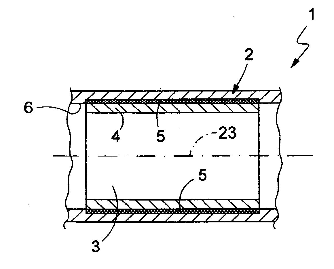
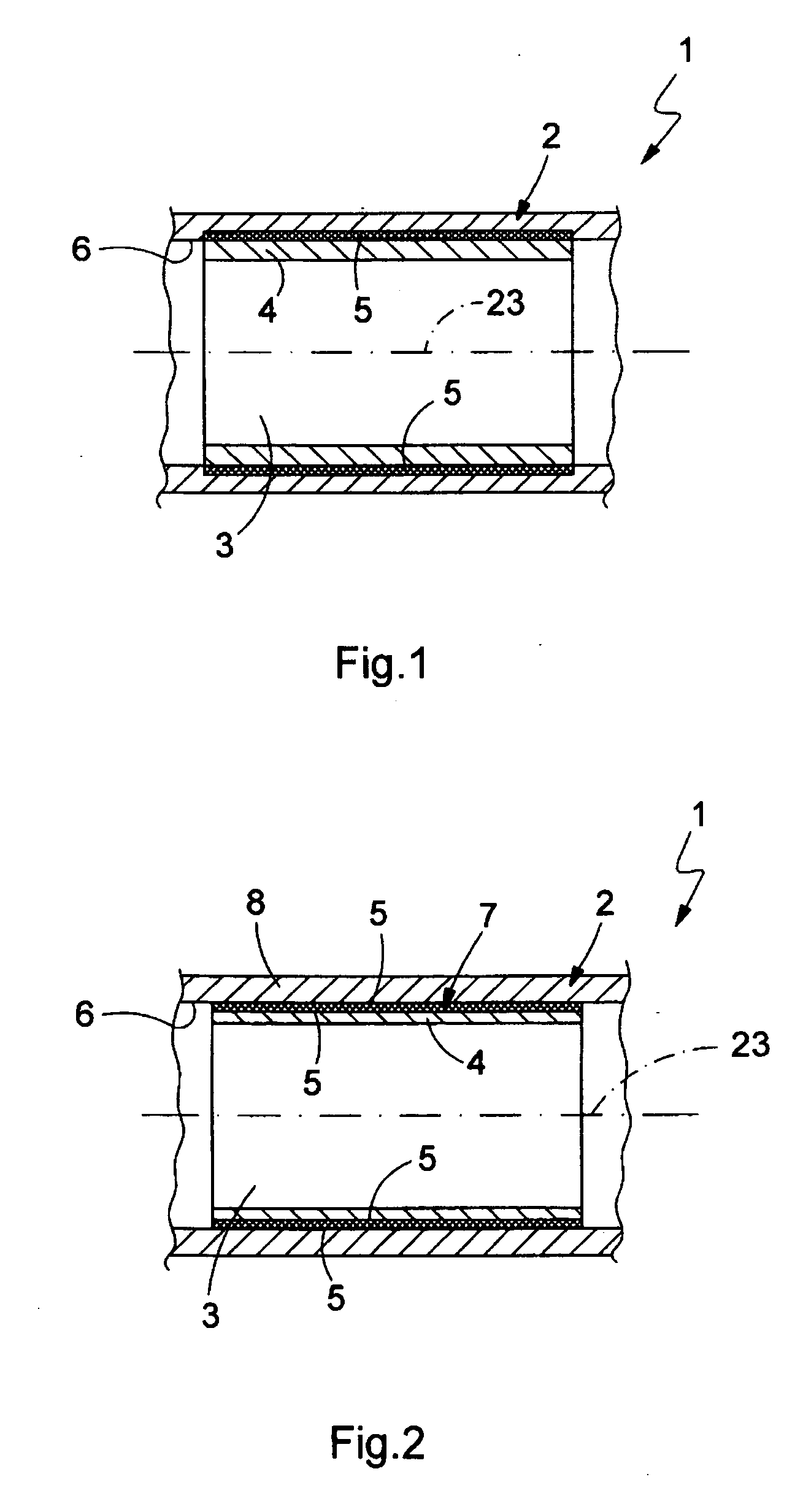
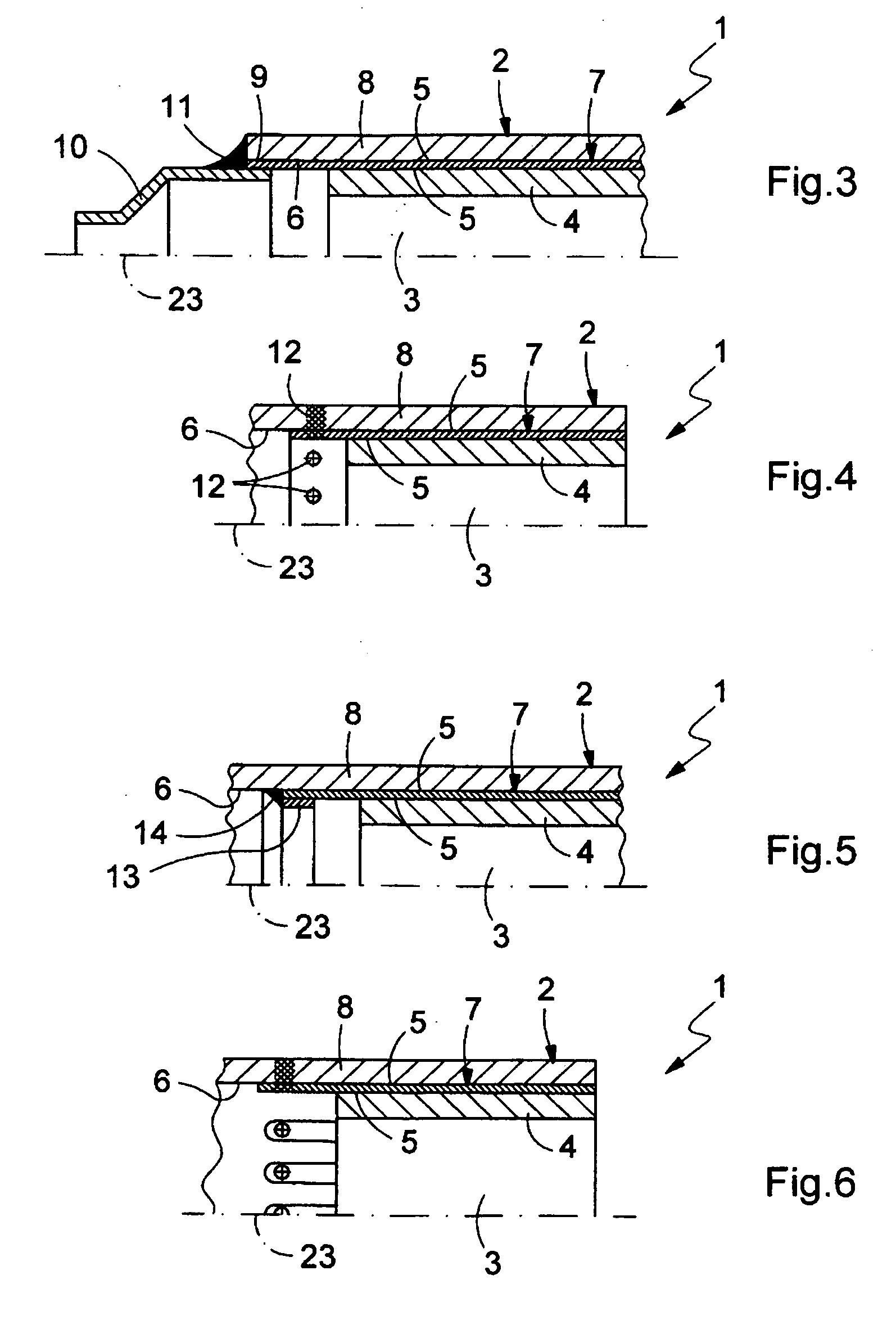
[0025] According to FIGS. 1 through 6, an inventive exhaust gas treatment device 1 which is suitable for installation in an exhaust system of an internal combustion engine, preferably installed in a motor vehicle, includes a housing 2, at least one exhaust gas treatment insert 3 arranged therein and a bearing material 4. The bearing material 4 sheaths the at least one exhaust gas treatment insert 3 on the circumference and is arranged radially between the respective exhaust gas treatment insert 3 and the housing 2 in the installed state. The bearing material 4 forms a support for the respective exhaust gas treatment insert 3 while at the same time forming axial fixation of same in the housing 2. To improve the axial fixation, at least one frictional structure 5 is provided according to this invention between the bearing material 4 and the housing 2. This at least one frictional structure 5 is designed so that it significantly increases the adhesive friction or adhesion between the b...


PUM

PropertyMeasurementUnit
frictional structureaaaaaaaaaa
circumferenceaaaaaaaaaa
tensionaaaaaaaaaa

Abstract

An exhaust gas treatment device for an exhaust gas system of an internal combustion engine, in particular of a motor vehicle, includes a housing and at least one exhaust gas treatment insert arranged in the housing and sheathed by bearing material on the circumference. To improve the axial fixation of the position of the exhaust gas treatment insert in the housing, at least one frictional structure is provided between the bearing material and the housing.

Description

FIELD OF THE INVENTION [0001] The present invention relates to an exhaust gas treatment device for an exhaust system of an internal combustion engine, such as a motor vehicle. The invention also relates to a method for manufacturing such an exhaust gas treatment device. BACKGROUND OF THE INVENTION [0002] An exhaust gas treatment device such as a catalytic converter or a particulate filter usually includes a housing and at least one exhaust gas treatment insert arranged therein, preferably a catalytic converter element or a particulate filter element. For storing the respective insert in the housing, the insert is sheathed on its circumference by a bearing material, preferably designed as a bearing mat. In the case of ceramic inserts in particular, e.g., in the form of monoliths, such bearing materials are at the same time used to secure the respective insert axially in the housing, preferably made of metal. To this end, the bearing material is put under radial tension in the install...

Claims


Application Information

Patent Timeline
Patent Type & Authority Applications(United States)
IPC IPC(8): B01D53/34F01N13/08
CPCF01N3/0211F01N3/2853Y02T10/20F01N2450/02F01N2350/00Y02T10/12Y02A50/20B01D53/00B01D53/92
Inventor WIRTH, GEORGWENZ, MARCOZACKE, PETER
Owner PUREM GMBH
Learn More