

Gas burner
a burner and gas technology, applied in the direction of burners, combustion types, combustion processes, etc., can solve the problems of serious hazard to the user and others around the burner, insufficient burning effect, etc., and achieve the effect of maintaining efficient burning
- Summary
- Abstract
- Description
- Claims
- Application Information
AI Technical Summary
Benefits of technology
Problems solved by technology
Method used
Image

Examples
Embodiment Construction
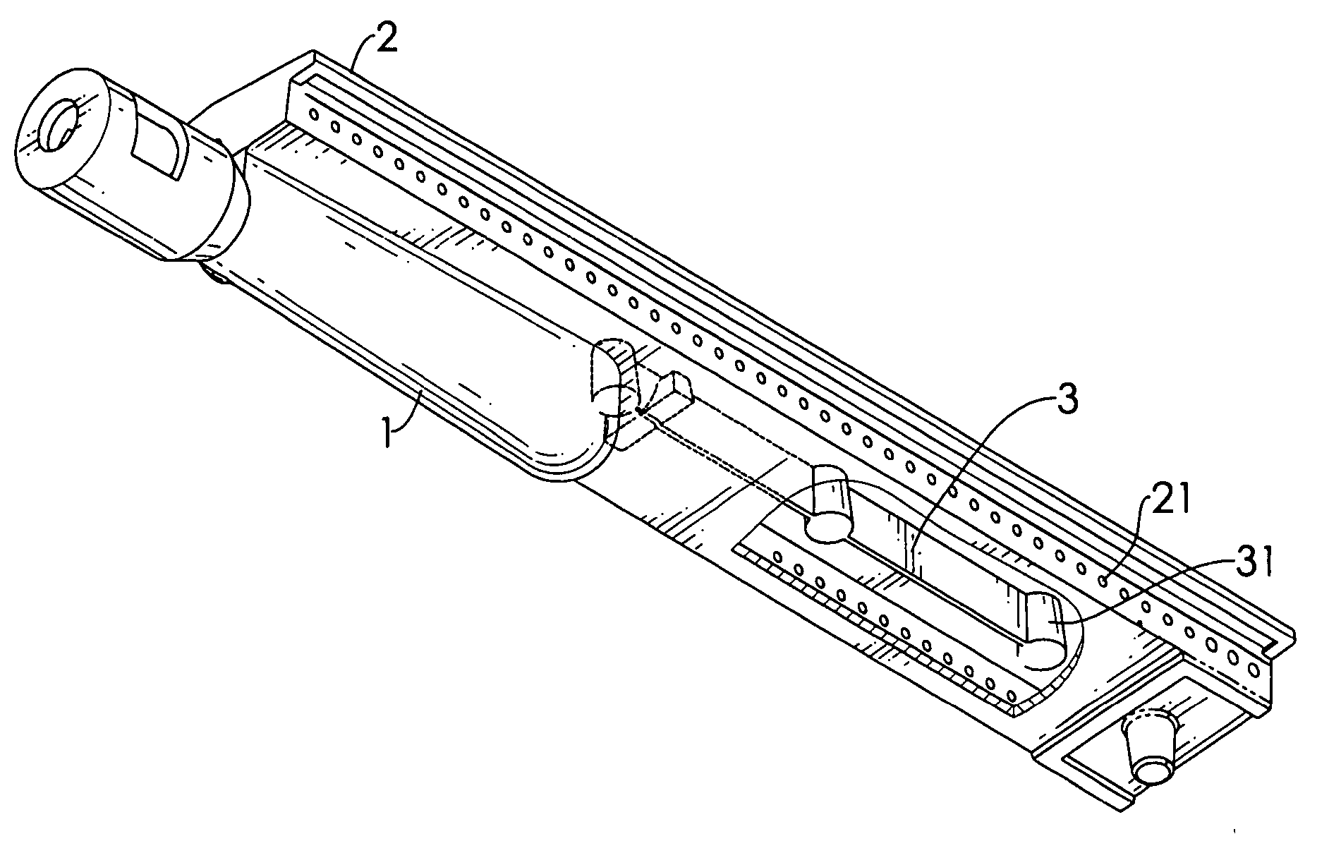
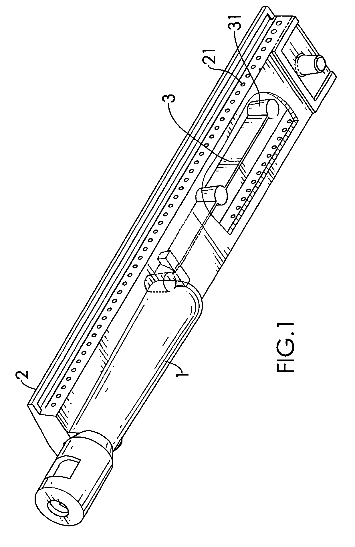
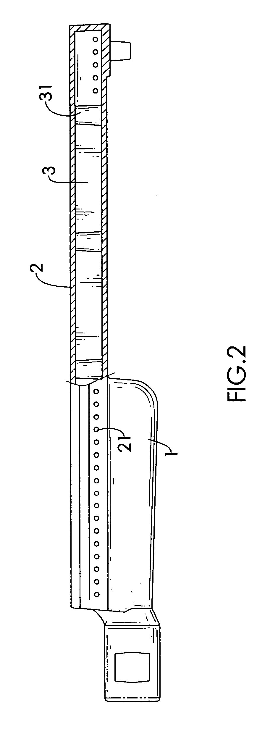
[0015] With reference to FIGS. 1, 2 and 3, it is noted that the gas burner in accordance with the present invention includes a cylindrical hollow body (1) and a top casing (2) integrally mounted on top of the body (1) and having multiple through holes (21) defined in two opposed side faces of the top casing (2) to communicate with an interior of the body (1). A supporting baffle (3) is formed inside the top casing (2) to engage with a bottom face and a top face thereof so as to increase the rigidity and stiffness of the top casing (2). Furthermore, multiple supporting posts (31) are formed along the supporting baffle (3) to increase the supporting effect of the supporting baffle (3). Furthermore, because the supporting baffle is made of a material having a melting point and rigidity higher than those of the material for the hollow body (1) and the top casing (2), the gas burner of the present invention is not easily distorted.
[0016] It is noted from the above description that with ...
PUM
 Abstract
Description
Claims
Application Information