Systems and methods for self-diagnosing LBIST

a self-diagnosis and system technology, applied in the field of electronic circuit testing, can solve the problems of increasing the chances of defects that may impair or impede the proper operation of the device, the cost of deterministic testing of all the combinations is generally too high for this methodology to be practical

Inactive Publication Date: 2007-01-11
KK TOSHIBA
View PDF23 Cites 24 Cited by
  • Summary
  • Abstract
  • Description
  • Claims
  • Application Information

AI Technical Summary

Problems solved by technology

Digital devices are becoming increasingly complex.
As the complexity of these devices increases, there are more and more chances for defects that may impair or impede proper operation of the devices.
If the number of possible input patterns and number of states is large, however, the cost of deterministic testing of all the combinations is generally too high for this methodology to be practical.
This conventional configuration has some drawbacks, however.
As a result, some of the information content is lost.
If the signature values do not match, the device under test has malfunctioned.
Consequently, data errors that propagate to the signature value in the MISR are combined with subsequent scan chain data, so that the specific cause of each error cannot be identified.
Thus, the signature value in the MISR does not contain sufficient information to localize the defect in the functional logic.

Method used


Image

  • Systems and methods for self-diagnosing LBIST
  • Systems and methods for self-diagnosing LBIST
  • Systems and methods for self-diagnosing LBIST

Examples


Embodiment Construction

[0028] One or more embodiments of the invention are described below. It should be noted that these and any other embodiments described below are exemplary and are intended to be illustrative of the invention rather than limiting.

[0029] As described herein, various embodiments of the invention comprise systems and methods associated with logic built-in self-test (LBIST) circuitry to identify the existence of logic circuit defects and provide data to localize the defect in the devices under test.

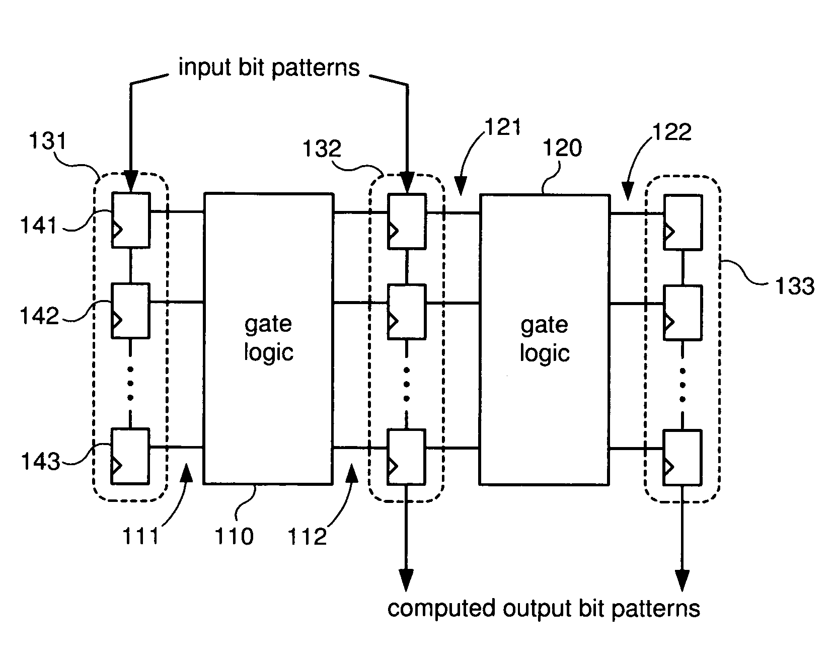
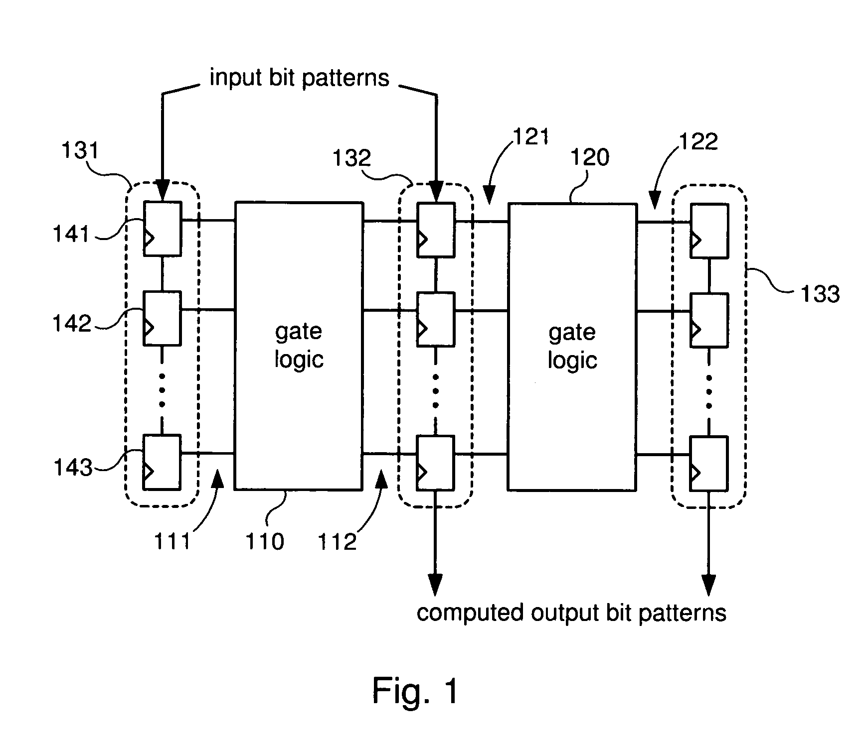
[0030] In one embodiment, LBIST circuitry, in conjunction with automated test equipment (ATE) is used to simultaneously process input patterns through some target logic within two “identical” devices, capturing and then comparing the computed patterns. The LBIST circuitry of each of the target devices consists of a pattern generator (e.g., a pseudorandom pattern generator, PRPG), scan chains, and multiple signal input generator (MISR). Both devices are connected to the ATE and are initialize...


PUM


Abstract

Systems and methods for performing logic built-in self-tests (LBISTs) in digital circuits. In one embodiment, a system has first and second target logic, each of which has LBIST circuitry incorporated therein. The system also includes comparison circuitry which is coupled to the first and second LBIST circuitry. The comparison circuitry is configured to detect differences between data generated by the LBIST circuitry of the first target logic and data generated by the LBIST circuitry of the second target logic (e.g., MISR signature values.) The comparison circuitry is also configured to provide information localizing the sources of the differences. In one embodiment, this localizing information comprises values from a test cycle counter, a scan shift counter and a set of XOR gates that compare the bits of the MISR values.

Description

BACKGROUND [0001] 1. Field of the Invention [0002] The invention relates generally to the testing of electronic circuits, and more particularly to systems and methods for using logic built-in self-test (LBIST) circuitry to identify the existence of a circuit defect and provide data to localize the defect in the device under test. [0003] 2. Related art [0004] Digital devices are becoming increasingly complex. As the complexity of these devices increases, there are more and more chances for defects that may impair or impede proper operation of the devices. The testing of these devices is therefore becoming increasingly important. [0005] Testing of a device may be important at various stages, including in the design of the device, in the manufacturing of the device, and in the operation of the device. Testing at the design stage ensures that the design is conceptually sound. Testing during the manufacturing stage may be performed to ensure that the timing, proper operation and performa...

Claims


Application Information

Patent Timeline
Patent Type & Authority Applications(United States)
IPC IPC(8): G01R31/28
CPCG01R31/318547
Inventor KIRYU, NAOKI
Owner KK TOSHIBA
Why Eureka
Try Eureka