Printing machine and corresponding method

a printing machine and corresponding technology, applied in printing presses, rotary presses, printing, etc., can solve the problems of increasing the cost of printing machines and the spatial requirement of printing machines, and achieve the effect of increasing the cost of printing machines and large spatial requirements

Inactive Publication Date: 2007-01-18
GOSS INT MONTATAIRE
View PDF24 Cites 13 Cited by
  • Summary
  • Abstract
  • Description
  • Claims
  • Application Information

AI Technical Summary

Benefits of technology

[0004] The presence of a dryer leads to the printing machine having a large spatial requirement and increases the cost of the printing machine.
[0005] An object of the present invention is to overcome these disadvantages and to provide a printing machine which has a smaller spatial requirement.

Problems solved by technology

The presence of a dryer leads to the printing machine having a large spatial requirement and increases the cost of the printing machine.

Method used


Image

  • Printing machine and corresponding method
  • Printing machine and corresponding method
  • Printing machine and corresponding method

Examples


second embodiment

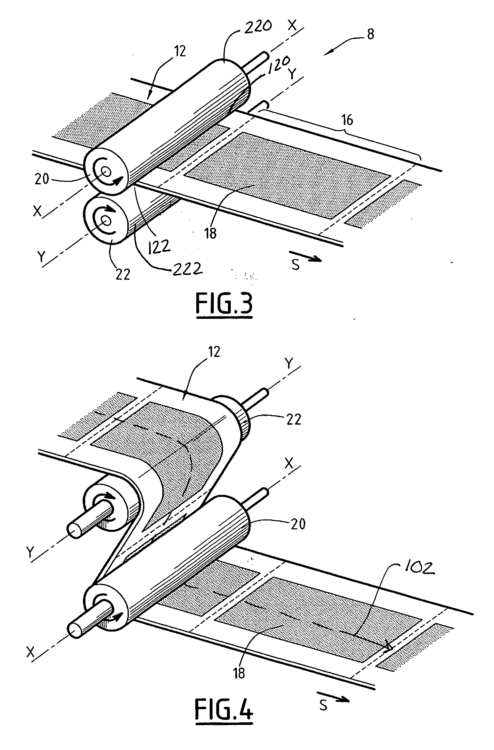
[0040]FIG. 4 illustrates a detail of a traction device 8 which differs from FIG. 3 in the following manner.

[0041] Elements which are similar have the same reference numerals.

[0042] The two traction rollers 20, 22 are arranged with mutual spacing so that they define a substantially S-shaped path 102 for the printed web 12. The S-shaped arrangement allows the rolling arc of the web to be increased on the driven rollers and therefore allows the efficiency of the traction module to be promoted owing to a capstan effect. Another device will then have to be associated with this traction module. This device will have to allow a level of downstream tension to be produced which is low but which is sufficient to bring about a level of upstream tension which is sufficiently high to pull the web out of the last printing assembly.

third embodiment

[0043]FIG. 5 illustrates a detail of a traction device 8 according to the invention which differs from the embodiment of FIG. 3 in the following manner. Similar elements have the same reference numerals.

[0044] The traction module 8 further includes two cleaning devices 30, 32. The quality of the image 18 on the printed web 12 is thus further improved.

[0045] The cleaning devices 30, 32 include cleaning bars 34, 36 which are in permanent contact with the traction surface 120, 122 of the rollers 20, 22. By way of example, the cleaning bars 34, 36 may include a rotating brush which is placed in contact with the surface to be cleaned or a web of materials placed in contact by means of a mechanical element. In both cases, the cleaning is facilitated by the action of a solvent. These techniques are used in particular for washing blankets on rotary offset presses.

[0046]FIG. 6 is a side view of a fourth embodiment of the traction device 8. This embodiment differs from the third embodiment ...

fifth embodiment

[0050]FIG. 7 illustrates the traction device 8 which comprises a variant of the cleaning devices 30, 32. Each cleaning device 30, 32 comprises two cleaning rollers 38, 40 which attract the ink and, for each of the cleaning rollers 38, 40, a washing device 50, 52.

[0051] The washing device 50, 52 is arranged at a distance a from the surface of the associated traction roller 20, 22 greater than the diameter of the corresponding cleaning roller 38, 40. Each cleaning roller 38, 40 can be moved between a cleaning position in which it is in contact with the associated traction roller 20, 22 and a washing position in which it is in contact with the associated washing device 50, 52. The two cleaning rollers 38, 40 of each cleaning device 30, 32 are controlled so as to alternately come into contact with the associated traction roller 20, 22.

[0052] That is to say, whilst one of the cleaning rollers 38 is in contact with the traction roller 20, the other cleaning roller 38 is in contact with t...


PUM

PropertyMeasurementUnit
mechanical tensionaaaaaaaaaa
mechanical tractionaaaaaaaaaa
diameteraaaaaaaaaa

Abstract

A rotary printing machine is provided which includes at least one printing unit suitable for printing on a continuous printing web of material to be printed and a cutting device which is suitable for cutting the web printed by the printing unit. The rotary printing machine further includes a traction device which is located downstream of the printing unit that is furthest downstream, and upstream of the cutting device. The traction device is suitable for applying a predetermined mechanical tension to the printed web being discharged from the printing unit that is furthest downstream.

Description

FIELD OF THE INVENTION [0001] The present invention relates to a rotary printing machine, of the type including at least one printing unit which is suitable for printing on a continuous printing web of material to be printed, and a cutting device which is suitable for cutting the web printed by the printing unit. BACKGROUND OF THE INVENTION [0002] Rotary printing machines are known from the prior art and include at least one printing unit which is provided with a pair of printing rollers, and a cutting device which is suitable for cutting the web printed by the printing unit. [0003] Known printing machines further include a dryer which is arranged between the last printing unit and the cutting device. This dryer is used to dry the ink which is deposited on the printed web in order to prevent the sheets from becoming marked in the cutting device. BRIEF SUMMARY OF THE INVENTION [0004] The presence of a dryer leads to the printing machine having a large spatial requirement and increase...

Claims


Application Information

Patent Timeline
Patent Type & Authority Applications(United States)
IPC IPC(8): B41F13/56
CPCB41F22/00B41F35/007B65H20/02B65H2301/121B65H2801/21B65H2404/14B65H2406/33B65H2601/251B65H2301/517
Inventor CHEVALIER, ANTOINEBERANGER, BERNARDOLLIVIER, PASCALBLANCHARD, ALAINSTANCHINA, ROGER
Owner GOSS INT MONTATAIRE
Why Eureka
Try Eureka