Transportation system of combined vehicles multi-coupled at highway speeds for electrical energy transfer and sharing

a technology of electrical energy transfer and transportation system, which is applied in the direction of transportation and packaging, electric propulsion mounting, coupling device connection, etc., to achieve the effect of large space and weight requirement, long charging time and large charging tim

Inactive Publication Date: 2016-12-27
TANG DERSHUEN ALLEN +1
View PDF2 Cites 43 Cited by
  • Summary
  • Abstract
  • Description
  • Claims
  • Application Information

AI Technical Summary

Benefits of technology

[0019]The goal of this invention is to remedy the current difficult situations in the deployment of electric vehicles, namely not enough charging stations, relatively long charging time (relative to gas-filling time), bulky and heavy batteries (resulting in large space and weight requirement on the vehicle that carries it, also relative to the space and weight requirement of gasoline with the same amount of usable energy). The solution proposed in this invention is to couple two or more vehicles to each other so that electric energy can be exchanged between the vehicles depending upon each individual vehicle's supply and demand. As vehicles which have excess electrical power join a cluster of vehicles, they are able to deliver power to those vehicles which have become more depleted of energy so that the cluster of vehicles can continue travelling without the need to stop for re-energizing.

Problems solved by technology

The related prior art cited above assume that the leading primary vehicles are still conventional electric vehicles with large batteries which require range-extending trailers as charging stations are not readily available.

Method used


Image

  • Transportation system of combined vehicles multi-coupled at highway speeds for electrical energy transfer and sharing
  • Transportation system of combined vehicles multi-coupled at highway speeds for electrical energy transfer and sharing
  • Transportation system of combined vehicles multi-coupled at highway speeds for electrical energy transfer and sharing

Examples


case 1

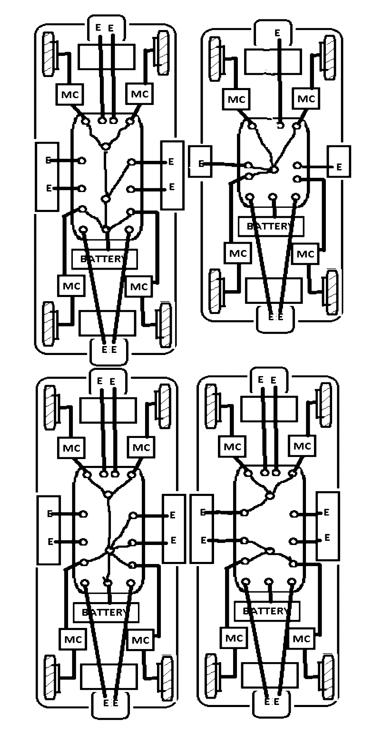
Process of Coupling Two Vehicles Together where Both have Standard Articulated Harnesses and which Will Connect in a Fore and Aft Configuration Leading to the Articulated Coupled Case

[0141]For the purpose of this illustration, the leading vehicle or vehicle cluster will be referred to as vehicle F, and the following vehicle or vehicle cluster will be referred to as vehicle A. Therefore, the coupler on the rear bumper of vehicle F will make contact with the coupler on the front bumper of vehicle A. In one configuration, the harness assembly may not be capable of extension. Under that limitation, only one of the two vehicles will extend and contract the harness assembly.

[0142]The path of the two vehicles to achieve coupling is negotiated and calculated by the main electronic control units of both vehicles so that vehicle A will be trailing vehicle F. If under manual control by a human driver, GPS like driving instructions of speed and direction are transmitted to the driver in terms o...

case 2

Process of Coupling Two Vehicles which Will Connect in a Lateral Configuration

[0152]For the purpose of this illustration, the left side vehicle or vehicle cluster will be referred to as vehicle L, and the right side vehicle or vehicle cluster will be referred to as vehicle R. Therefore, the coupler on the right side of vehicle L will make contact with the coupler on the left side of vehicle R. In one configuration, the harness assembly may not be capable of extension. Under that limitation, only one of the two vehicles will extend and contract the harness assembly.

[0153]After the negotiations have been made to identify the two vehicles which will be coupled as described above, the path of the two vehicles to achieve coupling is negotiated and calculated by the main electronic control units of both vehicles so that vehicle L will be traveling in the left lane and vehicle R will be traveling in the right lane. If under manual control by a human driver, GPS like driving instructions of...


PUM


Abstract

The transportation system in this invention provides vehicle coupling units which allow the electrical connections and reconfigurations of two or more vehicles together at highway speeds. The coupling unit provides for the bidirectional exchange of electrical power between these vehicles to meet the various power demands of each vehicle. The system is designed to permit coupling and decoupling process of the vehicles while they are traveling at highway speeds. To facilitate the coupling event, each vehicle will employ vehicle active steering, vehicle active suspension, and coupler joint articulation, which will be under vehicle computer control, and will employ vehicle to vehicle data communication. This transportation system allows the electric vehicles to electrically and mechanically couple together for flexible electrical power sharing to achieve the extension of the range of electrically powered vehicles to minimize the time needed for stationary re-charging of electrical vehicles required by electrical charging stations.

Description

CROSS-REFERENCE TO RELATED APPLICATIONS[0001]The present application is a Continuation-In-Part of U.S. application Ser. No. 14 / 269,072 filed May 2, 2014 (now abandoned) which claims priority to U.S. Provisional Application No. 61 / 818,880 filed May 2, 2013 which is incorporated by reference herein.BACKGROUND AND FIELD OF THE INVENTION[0002]Field of the Invention[0003]The present invention relates to a transportation system. More particularly, the present invention relates to a system for transportation of people and freight loads using electric vehicles (EVs) which have the capability of sharing electrical energy in a dynamic, flexible and bi-directional manner. The sharing is accomplished using a mechanical and electrical coupling system which can connect two or more vehicles into a cluster while they are in motion. Although the main objective of this invention is to increase the cruising range of EVs through collective energy sharing on the road, once these vehicles are connected f...

Claims


Application Information

Patent Timeline
Patent Type & Authority Patents(United States)
IPC IPC(8): B60L11/18B60W10/26
CPCB60L11/1818B60L11/18B60L11/1809B60W10/26Y02T10/7283Y10S903/907Y02T90/168Y02T90/128Y02T10/7266Y02T10/7275Y04S30/12Y04S30/14Y02T90/16Y02T10/7072Y02T90/14B60K1/00H01R13/6205B60L2200/28B60Y2200/91B60L53/16Y02T10/72Y02T10/70Y02T90/12Y02T90/167
Inventor TANG, DERSHUEN ALLENKNOPP, JAMES ARTHUR
Owner TANG DERSHUEN ALLEN
Why Eureka
Try Eureka