Zoom lens and imaging apparatus

a zoom lens and imaging apparatus technology, applied in the field of zoom lens and imaging apparatus, can solve the problems of insufficient miniaturization of the optical system, inability to secure, and short back focus at the wide angle end, and achieve the effects of small size, high performance and small siz

Active Publication Date: 2015-04-21
FUJIFILM CORP
View PDF31 Cites 0 Cited by
  • Summary
  • Abstract
  • Description
  • Claims
  • Application Information

AI Technical Summary

Benefits of technology

[0007]The present invention has been developed in view of the above circumstances. It is an object of the present invention to provide a zoom lens having high performance, which has a small size and a long back focus while having a high zoom ratio that exceeds 12.
[0019]According to the present invention, the fourth lens group substantially consists of a fourth-a lens group having positive refractive power and a fourth-b lens group having negative refractive power in this order from the object side in this order from the object side, and only the fourth-b lens group is configured to be moved toward the image side while focusing from the infinity to the close distance so that no large space is required between the fourth-a lens group and the fourth-b lens group. This allows the entire length of the fourth lens group to be short, thereby enabling miniaturization of the optical system. Furthermore, if the fourth-b lens group having negative refractive power approaches the fourth-a lens group, the back focus at the wide angle end can be long so that a space for a mirror, a filter, and the like of a single-lens reflex camera will be easily secured. Accordingly, a zoom lens having high performance, which is a small size and has a long back focus, while having a high zoom ratio can be obtained, and the sensitivity of movement of images associated with focusing movements can be appropriate.
[0020]According to the imaging apparatus of the present invention, the imaging apparatus can be configured to be compact and have high performance as well as can obtain excellent images using imaging elements because the zoom lens of the present invention is included therein.

Problems solved by technology

This does not allow the optical system to be sufficiently miniaturized.
Moreover, back focus at the wide angle end is likely to be short, and thereby, in the case that the zoom lenses disclosed in Japanese Unexamined Patent Publication No. 2009-009104 and Japanese Unexamined Patent Publication No. 2009-115874 are applied to a single-lens reflex camera, a space for a mirror, a filter, and the like cannot be secured.
Furthermore, both of the zoom lenses disclosed in Japanese Unexamined Patent Publication No. 2009-009104 and Japanese Unexamined Patent Publication No. 2009-115874 have a zoom ratio of approximately 10, which is not a sufficiently high zoom ratio.

Method used


Image

  • Zoom lens and imaging apparatus
  • Zoom lens and imaging apparatus
  • Zoom lens and imaging apparatus

Examples


example 1

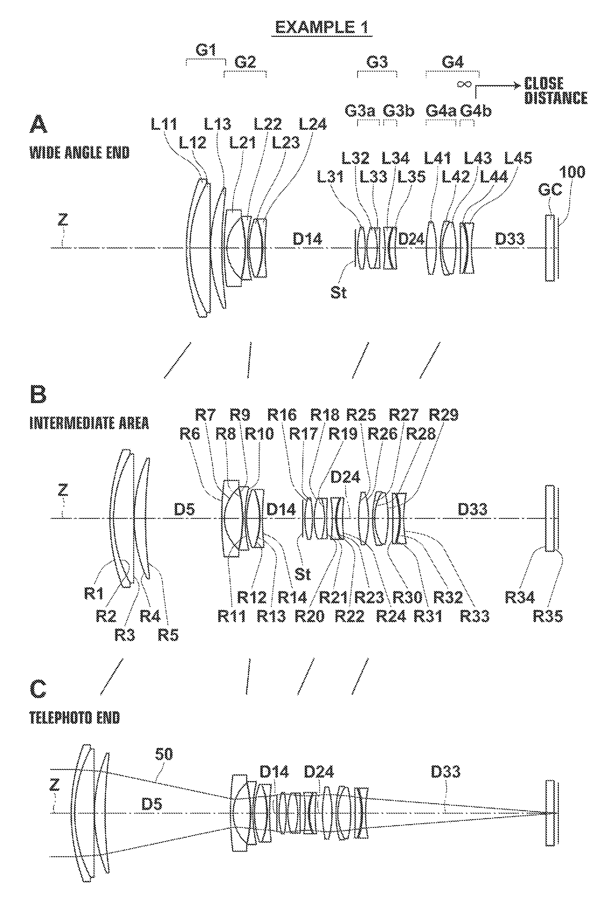
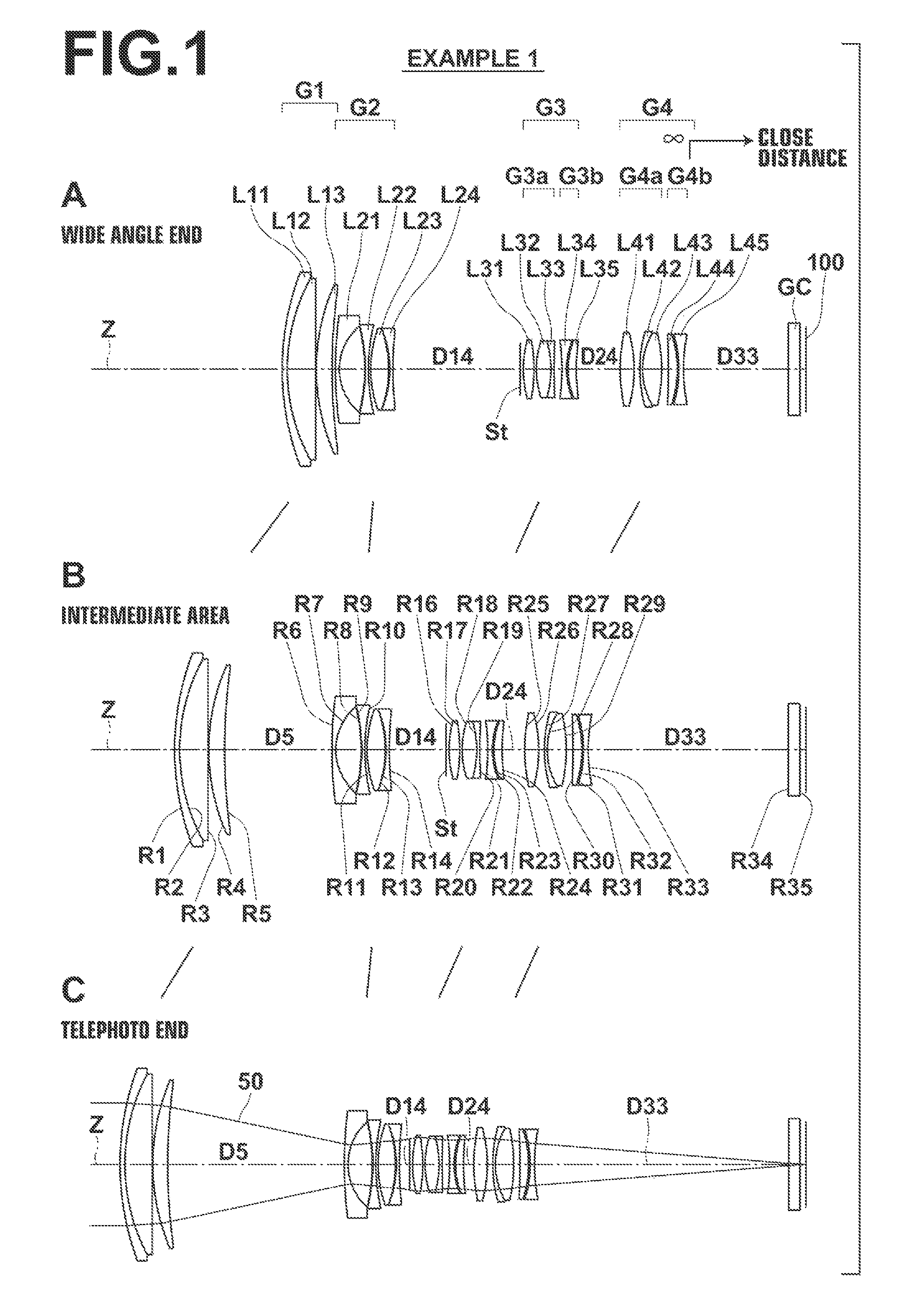
[0069]A, B, and C of FIG. 1 are diagrams illustrating configurations of the zoom lens according to Example 1 of the present invention.

[0070]The first lens group G1 of the zoom lens according to Example 1 substantially consists of a 1-1st lens L11 having a negative meniscus shape with a concave surface toward the image side, a 1-2nd lens L12 having a positive biconvex shape, and a 1-3rd lens L13 having a positive meniscus shape with a convex surface toward the object side in this order from the object side. A cemented lens is formed by cementing the 1-1st lens L11 and the 1-2nd lens L12 together.

[0071]The second lens group G2 substantially consists of a 2-1st lens L21 having a negative meniscus shape with a concave surface toward the image side, a 2-2nd lens L22 having a negative biconcave shape, a 2-3rd lens L23 having a positive biconvex shape, and a 2-4th lens L24 having a negative biconcave shape in this order from the object side. The 2-2nd lens L22 is a compound aspheric lens. ...

examples 2 and 3

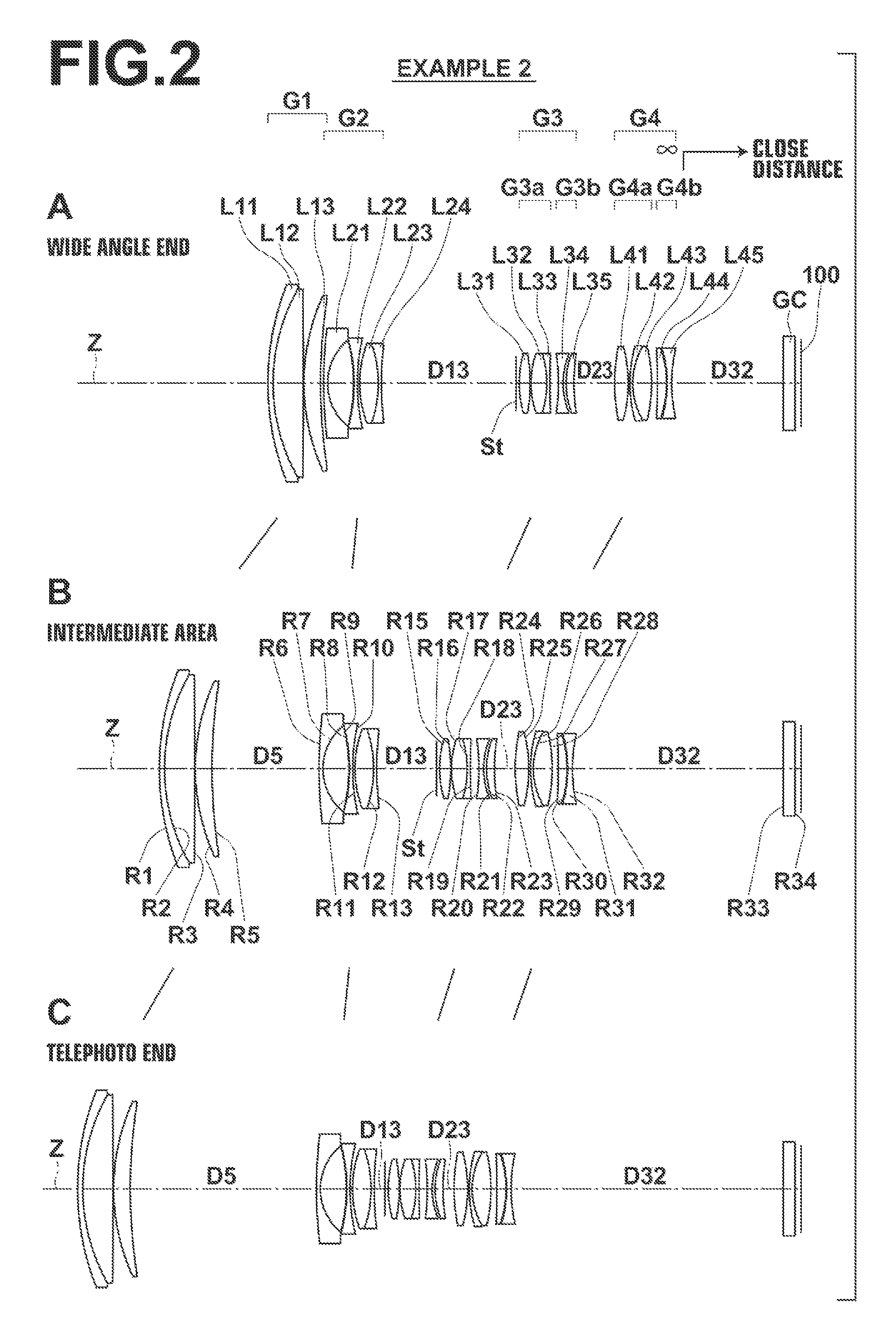
[0084]A, B, and C of FIG. 2 show configurations of the zoom lens according to Example 2 of the present invention, and A, B, and C of FIG. 3 show configurations of the zoom lens according to Example 3 of the present invention. The zoom lenses according to Examples 2 and 3 have substantially the same configuration as the zoom lens according to Example 1. However, Examples 2 and 3 differ from Example 1 in that a cemented lens is formed by cementing a 2-3rd lens L23 of the second lens group G2 and a 2-4th lens L24 thereof together, and accordingly, the surface numbers of the lenses on the image side of the 2-4th lens L24 are shifted by one from those of Example 1.

[0085]In the same manner as Example 1 described above, specific lens data of the zoom lens according to Example 2 is shown in Tables 4 through 6. In addition, specific lens data of the zoom lens according to Example 3 is shown in Tables 7 through 9. Note that each of the zoom lenses according to Examples 2 and 3 is configured s...

example 4

[0086]A, B, and C of FIG. 4 show configurations of the zoom lens according to Example 4 of the present invention. The zoom lens of Example 4 has substantially the same configuration as the zoom lens according to Example 1. However, the zoom lens of Example 4 differs from that of Example 1 in that the 2-3rd lens L23 of the second lens group G2 and the 2-4th lens L24 thereof are cemented to each other so as to form a cemented lens, and accordingly, surface numbers of the image-side surfaces from the 2-4th lens L24 are shifted by one from those of Example 1; and in that the third-b lens group G3b substantially consists of a 3-4th lens L34 having a positive meniscus shape with a convex surface toward the image side and a 3-5th lens L35 having a negative biconcave shape in this order from the object side.

[0087]In the same manner as for Example 1 described above, specific lens data of the zoom lens according to Example 4 is shown in Tables 10 through 12. Note that the zoom lens according ...


PUM


Abstract

A zoom lens substantially consists of a positive first lens group, a negative second lens group, a positive third lens group, and a positive fourth lens group in this order from the object side, wherein the distance between the first lens group and the second lens group increases and the distance between the second lens group and the third lens group decreases, and the distance between the third lens group and the fourth lens group decreases while changing magnification. The fourth lens group substantially consists of a positive fourth-a lens group composed of a biconvex-shape lens, a negative meniscus-shape lens, and a biconvex-shape lens and a negative fourth-b lens group composed of a positive meniscus-shape lens and a biconcave-shape lens in this order from the object side, and only the fourth-b lens group is moved toward the image side while focusing.

Description

CROSS-REFERENCE TO RELATED APPLICATIONS[0001]This application is a Continuation of PCT International Application No. PCT / JP2012 / 008256 filed on Dec. 25, 2012, which claims priority under 35 U.S.C. §119(a) to Japanese Patent Application No. 2011-284628 filed Dec. 27, 2011. Each of the above application(s) is hereby expressly incorporated by reference, in its entirety, into the present application.BACKGROUND OF THE INVENTION[0002]1. Technical Field[0003]The present invention relates to a zoom lens used in electronic cameras such as a digital camera, a video camera, a broadcasting camera, a movie camera, a surveillance camera, and the like, and to an imaging apparatus including the zoom lens.[0004]2. Description of the Related Art[0005]Conventionally, zoom lenses of a four group configuration, in which a fourth lens group is constituted by a fourth-a lens group and a fourth-b lens group and focus is performed by moving the fourth-b lens group on the rear side, have been proposed (Japan...

Claims


Application Information

Patent Timeline
Patent Type & Authority Patents(United States)
IPC IPC(8): G02B15/14G02B13/00G02B15/16G02B15/173G02B27/64
CPCG02B15/16G02B15/173G02B13/009G02B27/646G02B15/144113
Inventor TANAKA, TAKASHICHO, MICHIO
Owner FUJIFILM CORP
Why Eureka
Try Eureka