Leg fitness equipment motion guide

Inactive Publication Date: 2008-06-19
CHANG SRETER
View PDF4 Cites 16 Cited by
  • Summary
  • Abstract
  • Description
  • Claims
  • Application Information

AI Technical Summary

Benefits of technology

[0010]1. The present invention related to a unit of leg fitness equipment is essentially comprised of two guide tracks respectively and externally extending from both sides of a base of the equipment at a proper spacing in the same direction, both terminals of those two guide track are linked to become V-shaped or a triangle, or parallel guide tracks; a pair of pedals being alternatively stamped to push a crank, the crank then driving a transmission bracket to draw two pull rods to swing freely; and two guide pulleys each from a guide pulley bracket mounted to the terminal of each pull rod reciprocally traveling along both guide tracks. The linkage between both terminals of those two guide tracks disposed on both sides in V-shaped, triangle or parallel functions to reinforce the strength of both guide tracks so to prevent from deformation due to shaking or torsion while a user is treading the pair of pedals. Meanwhile, according to the treading direction is selected by the use either facing or turning back on the leg fitness equipment, both guide tracks in V-shaped, triangle, or parallel allow the treading in toe-out or toe-in exercise mode to simulate roller/in-line skating, skiing, treading,

Problems solved by technology

1. Complicated structure of technical configuration resulting in higher production cost;
2. Consuming larger space required for

Method used


Image

  • Leg fitness equipment motion guide
  • Leg fitness equipment motion guide
  • Leg fitness equipment motion guide

Examples


Embodiment Construction

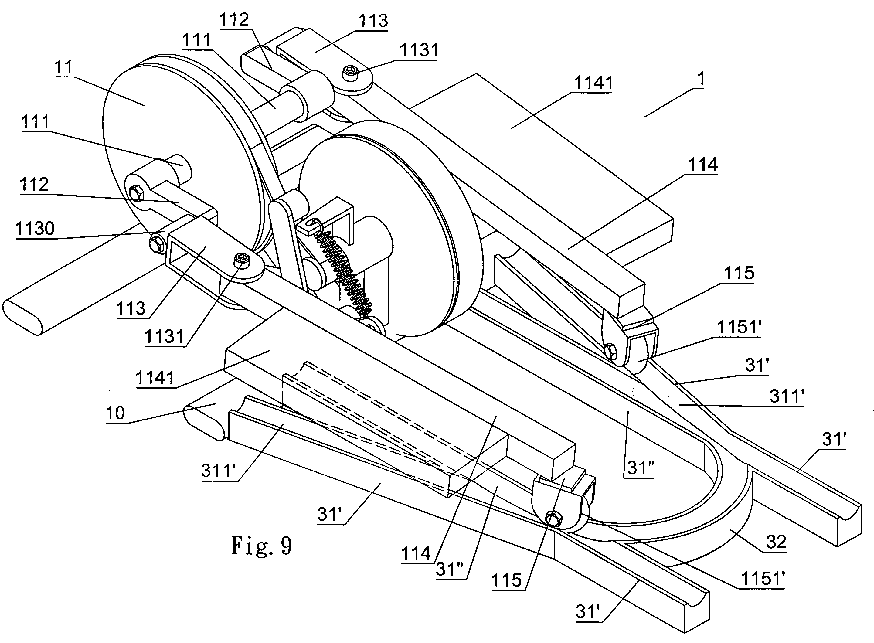
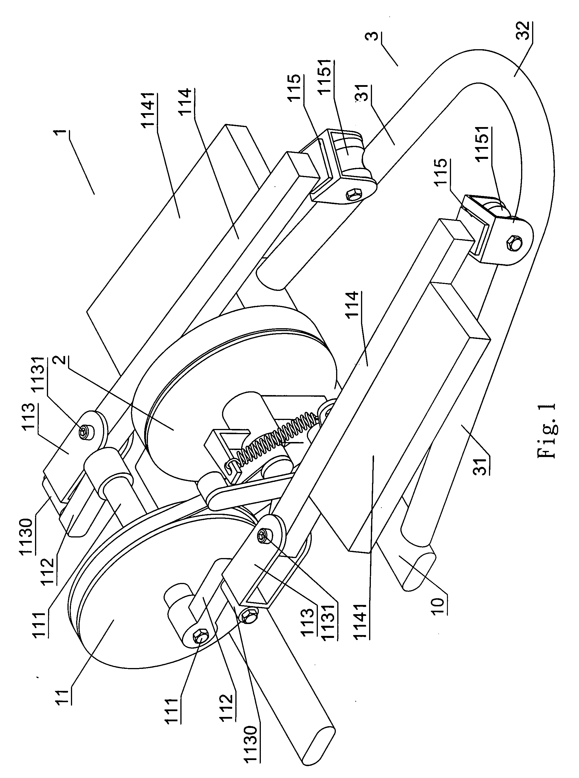
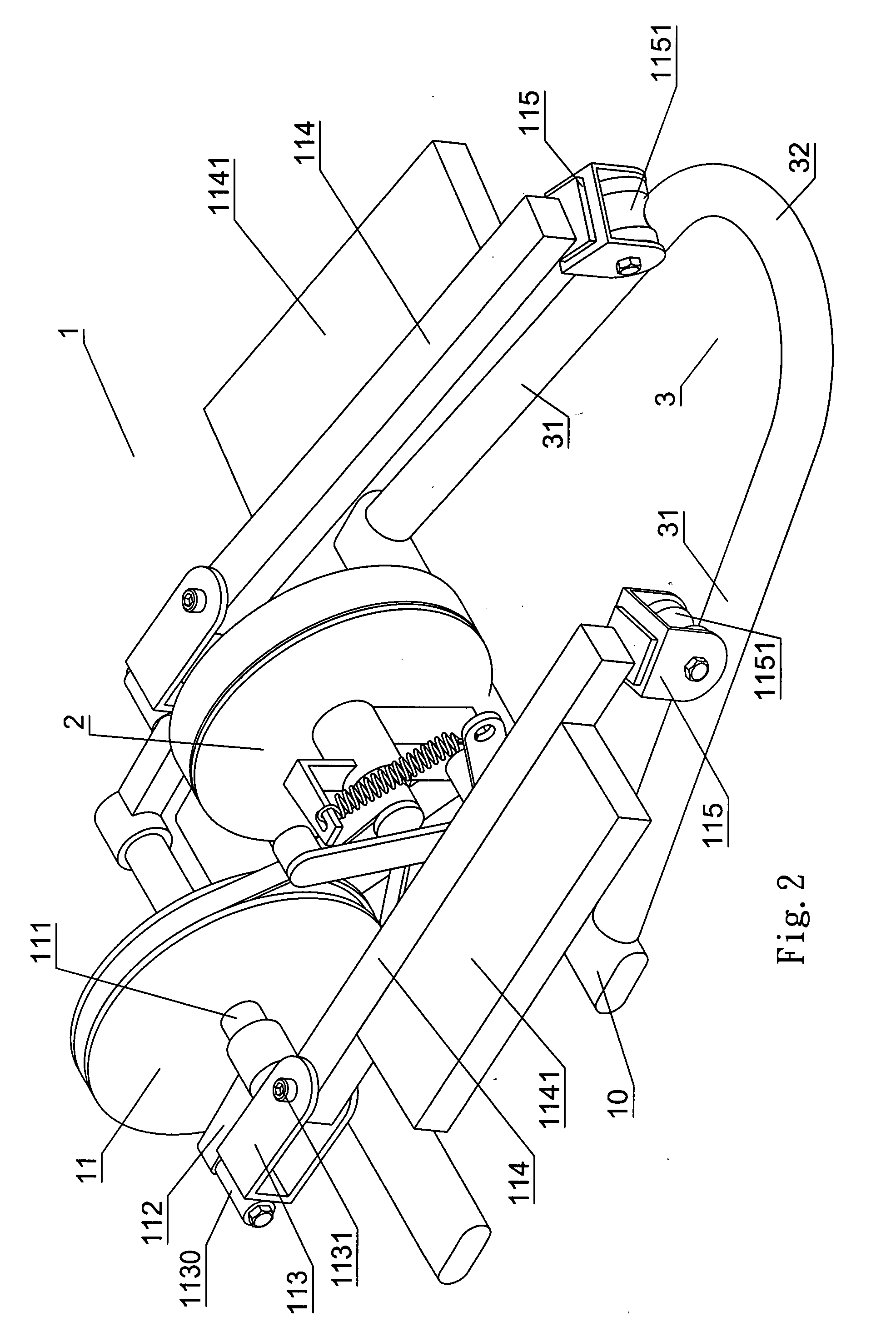
[0032]Referring to FIGS. 1˜6, a fitness equipment 1 of the present invention includes a transmission wheel 11 and a resistance control mechanism 2 (related to prior art, thus not elaborated herein) to control size of resistance against the transmission wheel 11 so to produce effects of adjusting and controlling the motion. As illustrated in FIG. 1, the present invention is essentially comprised of two cranks 112 are respectively and externally connected to both sides of a transmission shaft 111 of the transmission wheel 11. Each crank is inserted into a sleeve 1130 disposed at the front end of a transmission bracket 113; each transmission bracket 113 is connected to one end of a pull rod 114 with a pivot 1131; and each pull rod 114 is provided with a pedal 1141. Also referring to FIG. 4, the other end of each pull rod 114 is pivoted to a guide pulley bracket 115 with an axial shaft 1142, and a guide pulley 1151 is disposed in the guide pulley bracket 115. Both guide pulleys 1151 str...


PUM


Abstract

A leg fitness equipment includes two cranks respectively connected to both sides of a transmission shaft of a transmission wheel; each crank being inserted to a transmission bracket; each transmission bracket being pivoted to a pull rod; a pedal being provided to each pull rod; a terminal of each pull rod being pivoted to a guide pulley bracket containing a guide pulley or pulley; both guide pulleys or pulley striding over two sidetracks provided to both sides of a base of the fitness equipment; a user stepping on the pair of pedals to alternatively stamp thereon for both pull rods to slide back and forth on the guide track by means of the guide pulley; each pull rod follows the turning of the cranks at one end of the crank to be driven to its ascending and descending positions while reciprocally traveling by following expansion or reducing of the guide track; both pull rods drive the pair of pedals to produce oval turning; a reinforced section defined by a link between both terminals of two sidetracks to prevent the guide track from shaking and deformation due to torsion applied by the pair of pedals; and a user may stamp the pair of pedals in a position either facing or facing away from the transmission wheel of the fitness equipment to select travel motion in a toe-out or toe-in fashion in exercising stable simulation of roller/in-line skating, skiing, treading, walking, or twisting motion for achieving fitness purpose.

Description

BACKGROUND OF THE INVENTION[0001](a) Field of the Invention[0002]The present invention is related to a motion guide, and more particularly to one adapted to a leg fitness equipment that offers its user treading forward or backward to exercise toe in, toe out, or lateral movement to simulate roller / in-line skating, treading, walking, twisting, and foot racing including two guide tracks respectively and externally extending from both sides of a base of the equipment at a proper spacing, a reinforced section being defined by linking both terminals of those two guide tracks; a pair of pedals being stamped alternatively to push and turn a crank to further drive a transmission bracket; the transmission bracket then drawing two freely swinging pull rods; and two freely swinging guide pulley disposed on two guide pulley brackets respectively disposed on terminals of those two pull rods following the guide provided by those two guide tracks to engage reciprocal travel.[0003](b) Description o...

Claims


Application Information

Patent Timeline
IPC IPC(8): A63B22/20
CPCA63B22/0015A63B22/0064A63B2022/206A63B2022/0676A63B22/203A63B22/0664
Inventor CHANG, SRETER
Owner CHANG SRETER
Why Eureka
Try Eureka