Tethered or free flight blimp with collapsible tail fins

Inactive Publication Date: 2007-01-18
BARNES TRACY L
View PDF26 Cites 8 Cited by
  • Summary
  • Abstract
  • Description
  • Claims
  • Application Information

AI Technical Summary

Benefits of technology

[0013] The support rod of each tail fin is preferably flexible and arcuately curved about a center point which is located toward the tail end of the envelope, and the second end of the support rod, and thus the upper end portion of the panel, may be located longitudinally behind the tail end of the envelope so as to provide good leverage which contributes to the stability of the blimp under windy conditions.
[0017] The blimp of the present invention may also incorporate a control system which permits the orientation of the blimp with respect to the wind direction to be controlled during flight. This control system utilizes a pair of guy lines which are connected between the envelope and at least one of the fins, with the guy lines being connected to the fin at a point along the length of the support rod. Also, the guy lines are disposed in a V-shaped orientation when viewed in plan, and the control system includes actuators for drawing in a selected one of the guy lines while letting out the other of the guy lines. This causes the associated fin to warp in a manner analogous to “wing warpage” utilized in early aircraft. The warpage of the fin causes the tail end to move in a first direction and the nose end of the envelope to move in the opposite direction.

Problems solved by technology

However, the size has heretofore been limited by the need to be able to transport and store the blimp in a relatively small space.
Also, blimps with relatively large tail fins are vulnerable to wind damage when the blimp is assembled in the field.
As will be apparent, at this point in the assembly process, the envelope and fins are very vulnerable to damage, since the wind can whip the blimp around its attachment point on the mast.
As a result, several persons are required to hold and inflate the envelope, and then attach the fins, and these operations are particularly difficult in the case of relatively large blimps and when assembly is performed under windy conditions.
This design avoids some of the assembly problems at the point of use, but the inflatable fins are heavy and expensive.
Also, they require a relatively high internal pressure in order to provide the needed rigidity, and they thus tend to leak.

Method used


Image

  • Tethered or free flight blimp with collapsible tail fins
  • Tethered or free flight blimp with collapsible tail fins
  • Tethered or free flight blimp with collapsible tail fins

Examples


Embodiment Construction

[0032] The present inventions now will be described more fully hereinafter with reference to the accompanying drawings, in which several, but not all embodiments of the inventions are shown. Indeed, the invention may be embodied in many different forms and should not be construed as limited to the embodiments set forth herein. Rather, these embodiments are provided so that this disclosure will satisfy applicable legal requirements. Like numbers refer to like elements throughout.

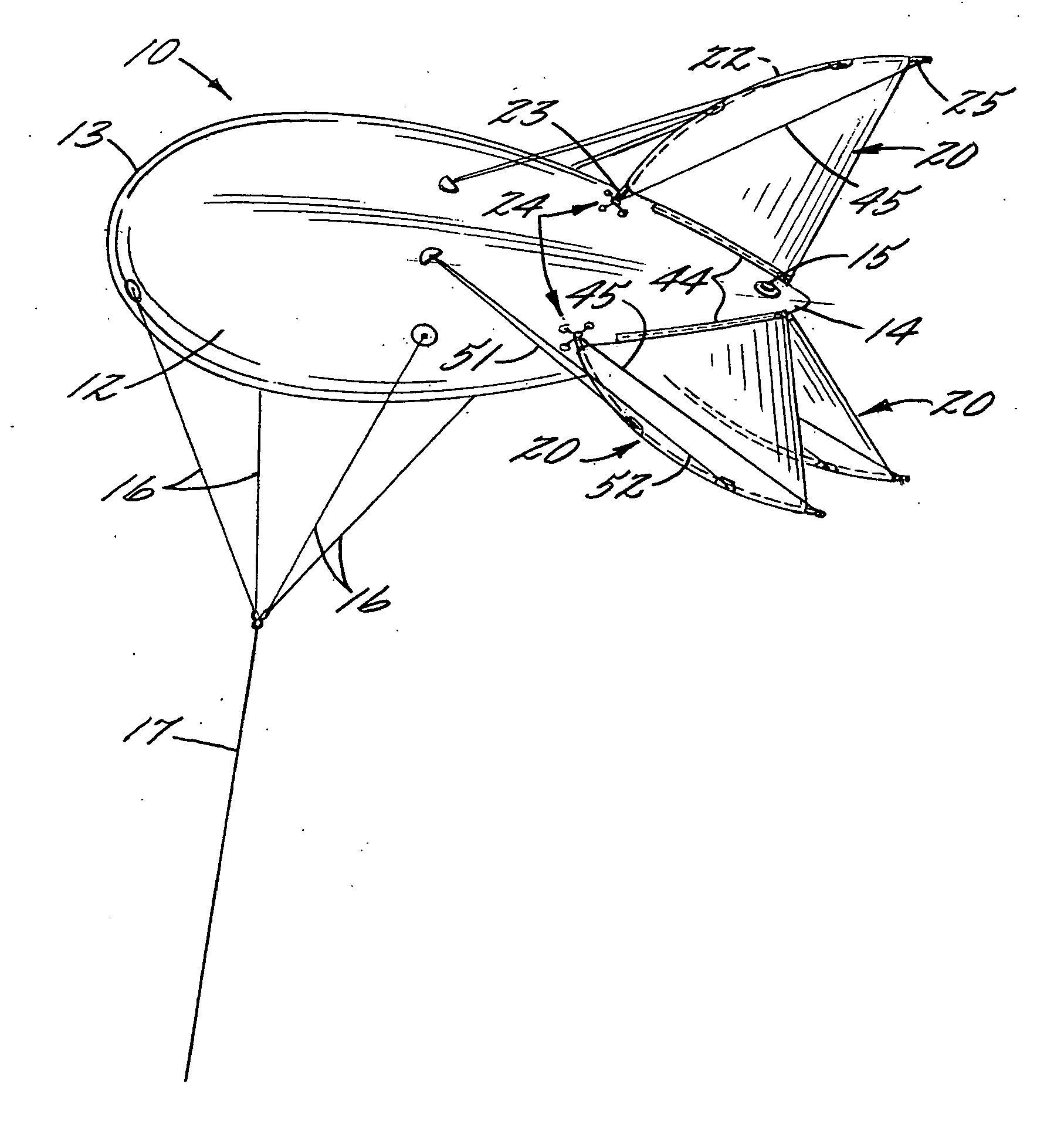
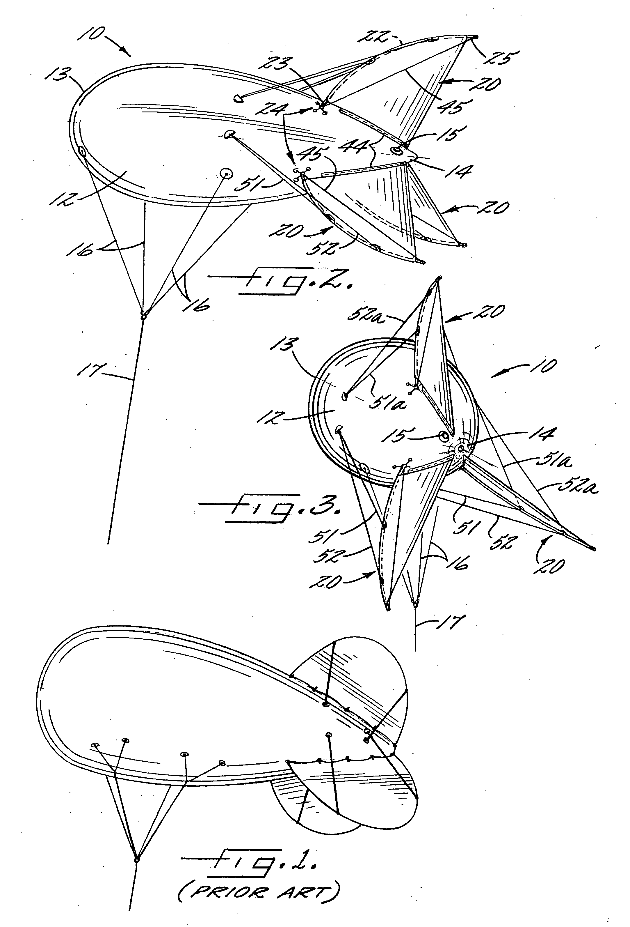
[0033] Referring more particularly to the drawings, FIGS. 2 and 3 illustrate a lighter than air aerodynamic blimp 10 which embodies the present invention and which comprises an elongate tubular aerodynamically shaped envelope 12 of flexible sheet material, such as polyurethane film. The envelope 12 defines a forward or nose end 13 and an opposite tail end 14, and so as to define a longitudinal direction therebetween.

[0034] The envelope 12 incorporates a conventional valve 15 adjacent the tail end for admitt...


PUM


Abstract

A lighter than air blimp which has either an aerodynamically shaped or a round envelope of flexible sheet material, and a plurality of stabilizing fins mounted in a circumferentially spaced apart arrangement about the tail end portion of the envelope. The tail fins are collapsible, to faciliate storage and transport to the point of use, and to also facilitate the rapid assembly and deployment of the blimp at the point of use, particularly under windy conditions. Also, the configuration of the fins may be adjusted during flight by a control system which permits adjustment of the orientation of the blimp with respect to the wind direction.

Description

BACKGROUND OF THE INVENTION [0001] The present invention is directed to a lighter than air blimp, which may be secured to the ground with a tether or designed for free flight. Such blimps are commonly used for advertising, or for supporting a payload, such as a surveillance camera, at an elevated location. [0002] As illustrated in FIG. 1, known blimps of the described type comprise a teardrop shaped envelope of flexible sheet material and which is filled with a lighter than air gas, such as helium. The envelope is typically 7 to 30 feet in length, although shorter and longer lengths, up to 100 feet or more, are known. Also, the envelope mounts several tail fins to keep the envelope oriented and stable in the wind. The tail fins may be rigid and composed of a structural framework of metal or wood which is covered with a suitable flexible fabric. In the known blimp illustrated in FIG. 1, the tail fins are of generally semi-circular outline, and a pair of guy lines or rods extend later...

Claims


Application Information

Patent Timeline
IPC IPC(8): B64B1/02
CPCB64B1/20B64B1/02
Inventor BARNES, TRACY L.
Owner BARNES TRACY L
Why Eureka
Try Eureka