

Light-emitting diode drive circuit, light source device, and display device
- Summary
- Abstract
- Description
- Claims
- Application Information
AI Technical Summary
Benefits of technology
Problems solved by technology
Method used
Image

Examples
first embodiment
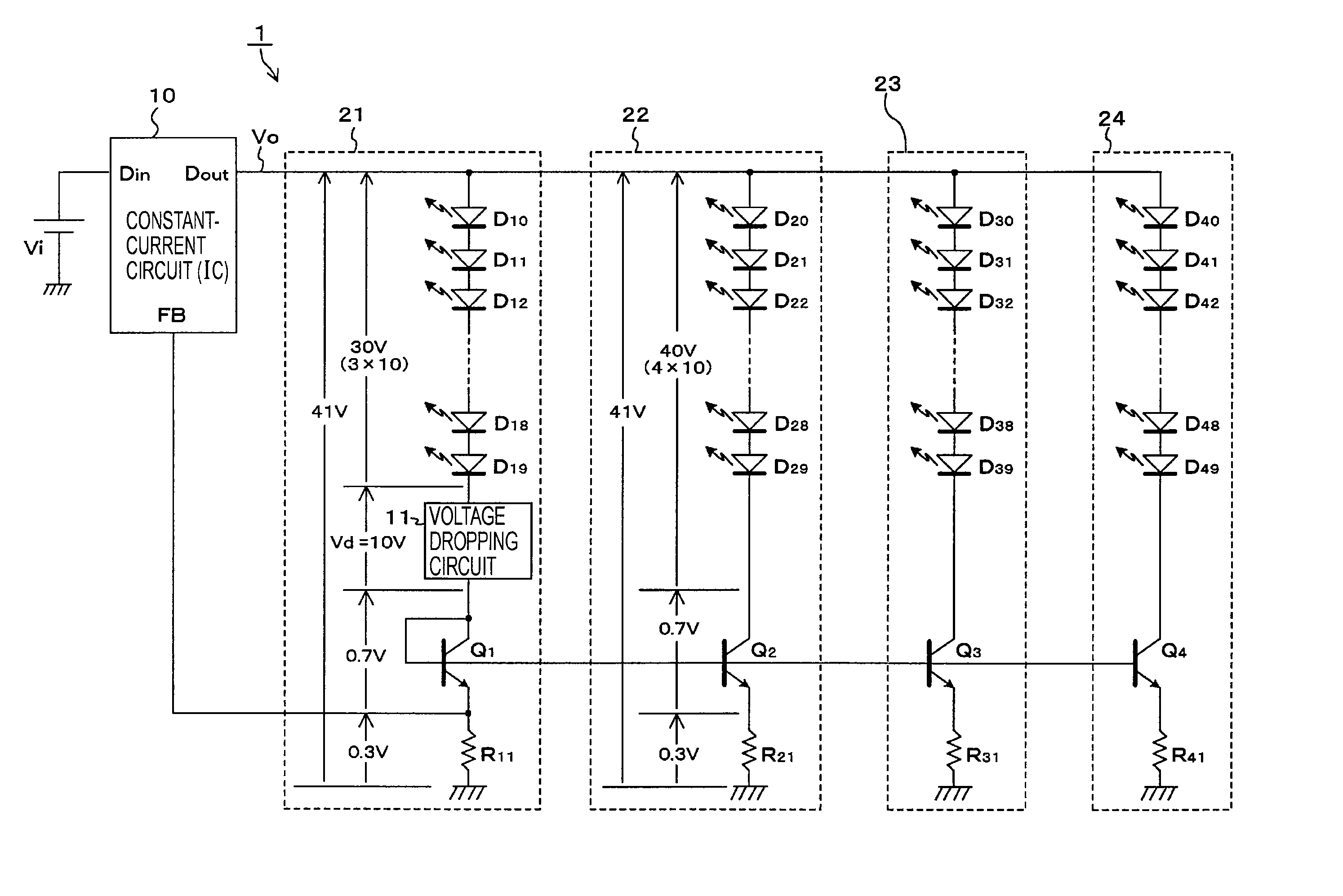
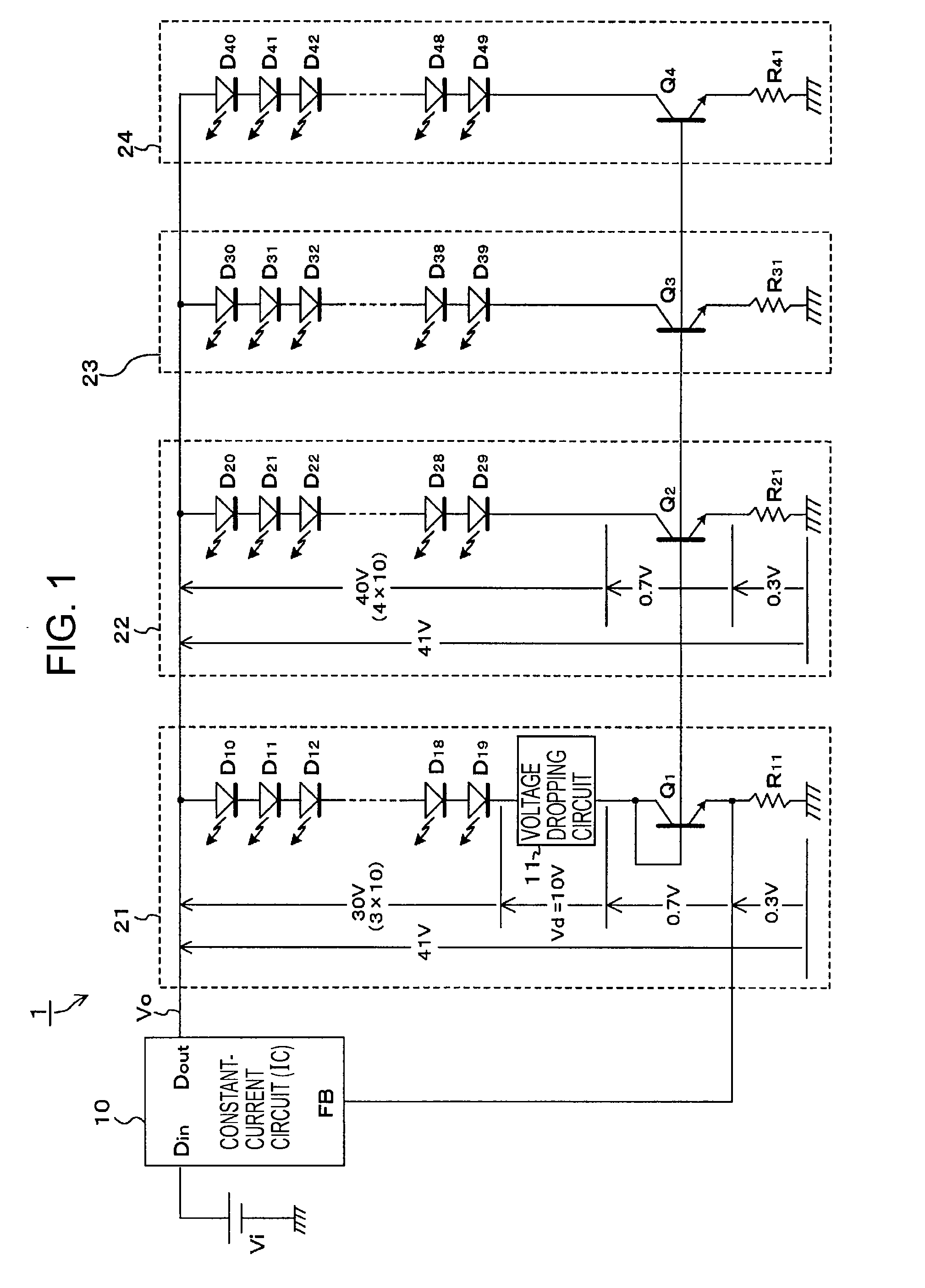
[0069]FIG. 1 shows an example of the configuration of the LED drive circuit 1 according to the present invention. In FIG. 1, the same parts as those in FIGS. 14 and 15 are designated by the same reference numerals, and repeated descriptions thereof will be omitted.
[0070] The configuration of the LED drive circuit 1 shown in FIG. 1 is the same as those shown in FIGS. 14 and 15 except for a voltage dropping circuit 11 included in the first series drive circuit 21. More specifically, the basic configuration of the LED drive circuit 1 includes the first to fourth series drive circuits 21 to 24 each including 10 series-connected LEDs, which are connected in parallel with the output of the constant-current circuit 10. The constant-current circuit 10 operates to allow a predetermined constant amount of current to flow through the first series drive circuit 21 serving as the reference on the basis of the amount of current detected by the detection resistor R11 in the first series drive circ...
second embodiment
[0128] On the assumption that the base-emitter voltage (VBE1) of the transistor Q1 is 0.7 V, the resistances of the resistors Rv1 and Rv2 are selected on the basis of equation (2), thereby setting the collector-emitter voltage (VCE1) to 10.7 V. In the first series drive circuit 21, as shown in FIG. 10, it can be regarded that there is a voltage drop of 10 V (10.7−0.7) serving as the collector-base voltage of the transistor Q1. In contrast, in the case of FIG. 1, the collector and the base of the transistor Q1 are connected to each other. Thus, the potential difference between the collector and the base is zero, and hence the collector-emitter voltage (VCE1) is 0.7 V, which is the same as the base-emitter voltage. In other words, instead of the omitted voltage dropping circuit 11, a certain potential is generated as the collector-base voltage of the transistor Q1, thereby causing the voltage drop Vd.
[0129] In the circuit shown in FIG. 10, as in FIG. 9, on the assumption that the vol...
PUM
 Abstract
Description
Claims
Application Information