
Wireless indicating apparatus

a technology of indicating apparatus and wires, which is applied in the direction of instruments, climate sustainability, computing, etc., can solve the problems of “trigeminal nerve” damage, mouse injury risk, and wrist-tunnel syndrome, and achieve the effect of greater freedom and convenien

Inactive Publication Date: 2007-01-18
GIGA BYTE TECH CO LTD
View PDF4 Cites 8 Cited by
  • Summary
  • Abstract
  • Description
  • Claims
  • Application Information

AI Technical Summary

Benefits of technology

The present invention provides a wireless indicating apparatus that allows users to operate it with greater freedom and convenience than previous devices. It records differences in orientation and position to allow users to use it in portrait and landscape orientations. The apparatus includes an operating unit, orientation-sensing unit, signal-processing unit, wireless emitting unit, and power supply device. The orientation-sensing unit includes a vertical sensing unit and a horizontal sensing unit to detect orientation. The apparatus can enter a power-saving mode and can be easily learned and operated by users with little training. It reduces the risk of injury or harm due to incorrect gestures and is suitable for new users. The technical effects of the invention include increased freedom and convenience, reduced harm from incorrect gestures, and improved user experience.

Problems solved by technology

When the user operates the mouse for a long time or in an unergonomical manner, the actions will oppress the nerve and cause a wrist-tunnel syndrome.
Because some users operate a mouse by leaning their hand against the rim of the table, it will cause “trigeminal nerve” damage.
Therefore, there exists some risk of injury from using the mouse.
Furthermore the mouse that needs to be operated upon a flat surface limits the freedom of the use of the mouse.
However, the device must still be operated upon a flat surface.
It is inconvenient for the user and requires some time to learn the operation of the mouse.

Method used


Image

  • Wireless indicating apparatus
  • Wireless indicating apparatus
  • Wireless indicating apparatus

Examples


Embodiment Construction

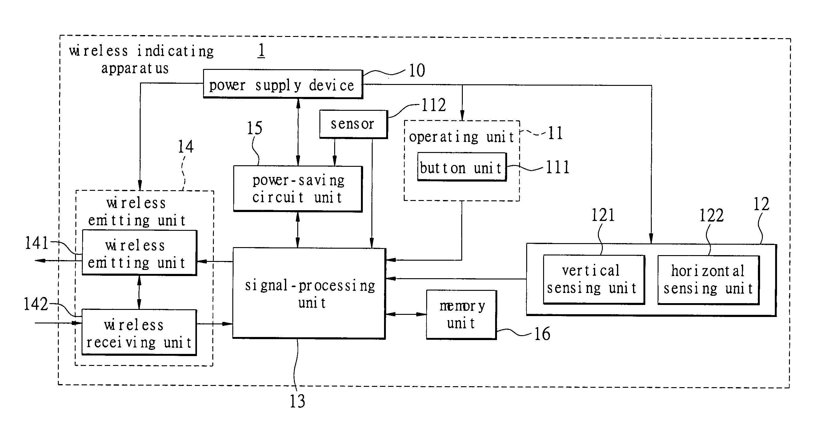
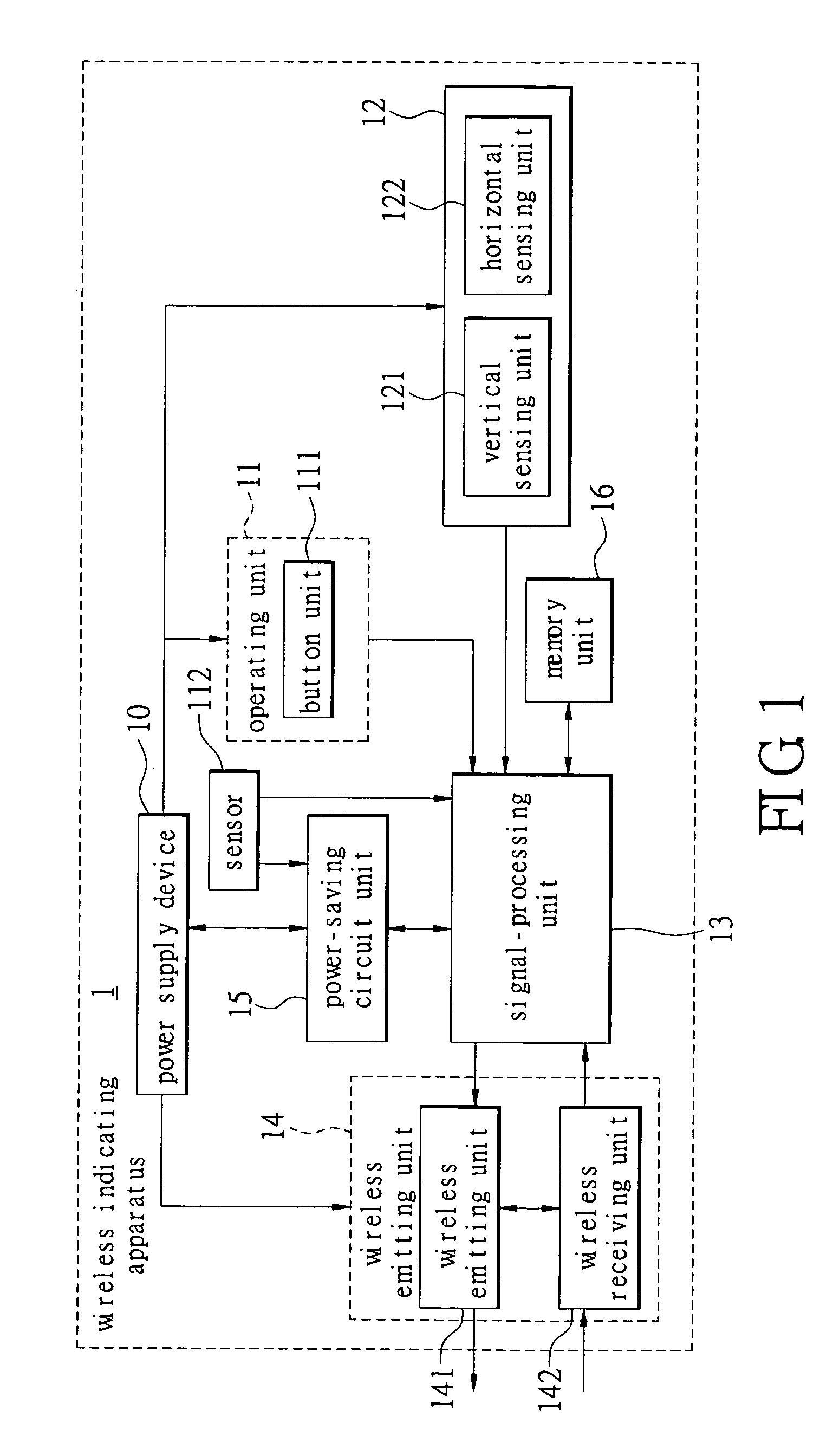
[0017]FIG. 1 is a block diagram of the wireless indicating apparatus of the present invention. The wireless indicating apparatus 1 comprises an operating unit 11, an orientation-sensing unit 12, a signal-processing unit 13, a wireless emitting unit 14 and a power supply device 10. The power supply device 10 supplies the power for all units of the wireless indicating apparatus 1. The operating unit 11 is an input device for inputting an instruction by the user. The operating unit 11 includes at least one button unit 111. The orientation-sensing unit 12 is an orientation sensor for sensing or judging the orientation of the wireless indicating apparatus 1. The orientation-sensing unit 12 comprises a vertical sensing unit 121 and a horizontal sensing unit 122. The vertical sensing unit 121 is a gravity-sensing unit for sensing the difference between the orientation of the Earth's gravity and the vertical orientation of the wireless indicating apparatus 1 to obtain a vertical orientation...


PUM


Abstract

A wireless indicating apparatus solves the issues of operating freedom and the inconvenience of wireless input devices of the prior art. The present wireless indicating apparatus records the difference between a horizontal orientation, an operating cursor's position, and the difference between the vertical orientation and the operating cursor's position. Therefore, the user can use the wireless indicating apparatus freely. The wireless indicating apparatus comprises an operating unit, an orientation-sensing unit, a signal-processing unit, a wireless emitting unit and a power supply device. A computer system receives the operation signal via a wireless receiving device and controls the movement, clicking or selection of the cursor upon a screen. Therefore, the operation of the wireless indicating apparatus of the present invention is not limited to a flat surface. It increases the freedom of operation and convenience, and reduces injuries such as those caused by incorrect use of a mouse.

Description

BACKGROUND OF THE INVENTION [0001] 1. Field of the Invention [0002] The present invention relates to a wireless indicating apparatus and in particular, to the operation of a wireless indicating apparatus and system that is not limited to use upon a flat surface and in which the user can use the wireless indicating apparatus by employing hand gestures. [0003] 2. Description of Related Art [0004] In order to conveniently operate an electrical apparatus (such as a projecting camera, a PC or a game machine), a user operates the operation system of an electrical apparatus via an input device. The most popular input devices are currently mice, keyboards, handwriting input devices, etc. Because Microsoft Operating Systems are the most popular operating systems, the mouse has become the most common indicating apparatus for most computer users. At the same time, due to the development of wireless communication technology, a lot of wireless input devices (e.g. wireless mice) have been designe...

Claims


Application Information

Patent Timeline
Patent Type & Authority Applications(United States)
IPC IPC(8): G09G5/08
CPCG06F1/3203G06F1/3231G06F1/3259Y02B60/148G06F3/03545Y02B60/1253Y02B60/1289G06F3/0346Y02D10/00
Inventor CHIEN, HUAN-WEN
Owner GIGA BYTE TECH CO LTD
Learn More