Position-measuring device

a technology of measuring device and positioning device, which is applied in the direction of measurement device, sensor output conversion, instruments, etc., can solve the problems of unfavorable scanning unit enlargement, relative cost of manufacture,

Active Publication Date: 2007-01-18
DR JOHANNES HEIDENHAIN GMBH
View PDF8 Cites 17 Cited by
  • Summary
  • Abstract
  • Description
  • Claims
  • Application Information

AI Technical Summary

Benefits of technology

[0005] Example embodiments of the present invention may provide a position-measuring device in which as compact a construction of the scanning unit as possible may be achieved.
[0006] According to example embodiments of the present invention, it is provided to arrange the elements in the scanning unit such that beams of rays impinging on the measuring graduation propagate diffracted in the direction of the scanning unit, where they pass through first grating structures. Subsequently, the partial beams of rays impinge on the reflector element, from which a back reflection takes place in the direction of the measuring graduation, before the partial beams of rays then pass through second grating structures and impinge again on the measuring graduation. The grating structures are arranged such that, upon the first and second passing through of the partial beams of rays, a defined lens effect on the partial beams of rays results.
[0007] Instead of complex and voluminously constructed retroreflector elements based on prisms, the scanning unit hereof provides a unit that includes one or more simple reflector elements and first and second grating structures having certain optical lens effects. The grating structures take over a retroreflector functionality in this connection, and also a scanning grating functionality. In this manner, a planar construction of this unit may be implemented which may make possible a simple and cost-effective assembly of same.
[0009] In response to passing through the first grating structures, there results, as the lens effect, a deflecting effect oriented antiparallel to the direction of incidence in the measuring direction, as well as a focusing effect perpendicular to the measuring direction, toward the reflector element. In response to the passage through the second grating structures, there results, as the lens effect, a deflecting effect in the measuring direction as well as at least one collimating effect perpendicular to the measuring direction.
[0025] According to an example embodiment of the present invention, a position-measuring device for recording a relative position of a scanning unit and a measuring graduation movable with respect to the scanning unit in at least one measuring direction includes: a plurality of grating structures and at least one reflector element arranged on the scanning unit, elements in the scanning unit arranged such that beams of rays diffracted by the measuring graduation propagate in a direction of the scanning unit and pass through first grating structures, impinge subsequently onto the reflector element, from which a retroreflection occurs in a direction of the measuring graduation, then pass through second grating structures and then once again impinge upon the measuring graduation, the first grating structures and the second grating structures adapted to provide a defined lens effect on the partial beams of rays in response to each respective passing through of the partial beams of rays.
[0026] The first grating structures and the second grating structures may be configured such that: passing through the first grating structures provides, as the lens effect, a deflecting effect oriented antiparallel to a direction of incidence in the measuring direction and a focusing effect perpendicular to the measuring direction, toward the reflector element; and passing through the second grating structures provides, as the lens effect, a deflecting effect in the measuring direction and at least one collimating effect perpendicular to the measuring direction.

Problems solved by technology

The reflector elements based on various prism variants, conventional for position-measuring devices, represent component parts that are relatively costly to manufacture.
In addition, these component elements take up a great deal of space, and this results in an undesired enlargement of the scanning unit.
The first and second grating structures may be arranged such that, because of the resulting deflecting effects during the first and the second passage, an error in alignment results between the points of impingement of the partial beams of rays on the first and second grating structures.

Method used


Image

  • Position-measuring device
  • Position-measuring device
  • Position-measuring device

Examples


Embodiment Construction

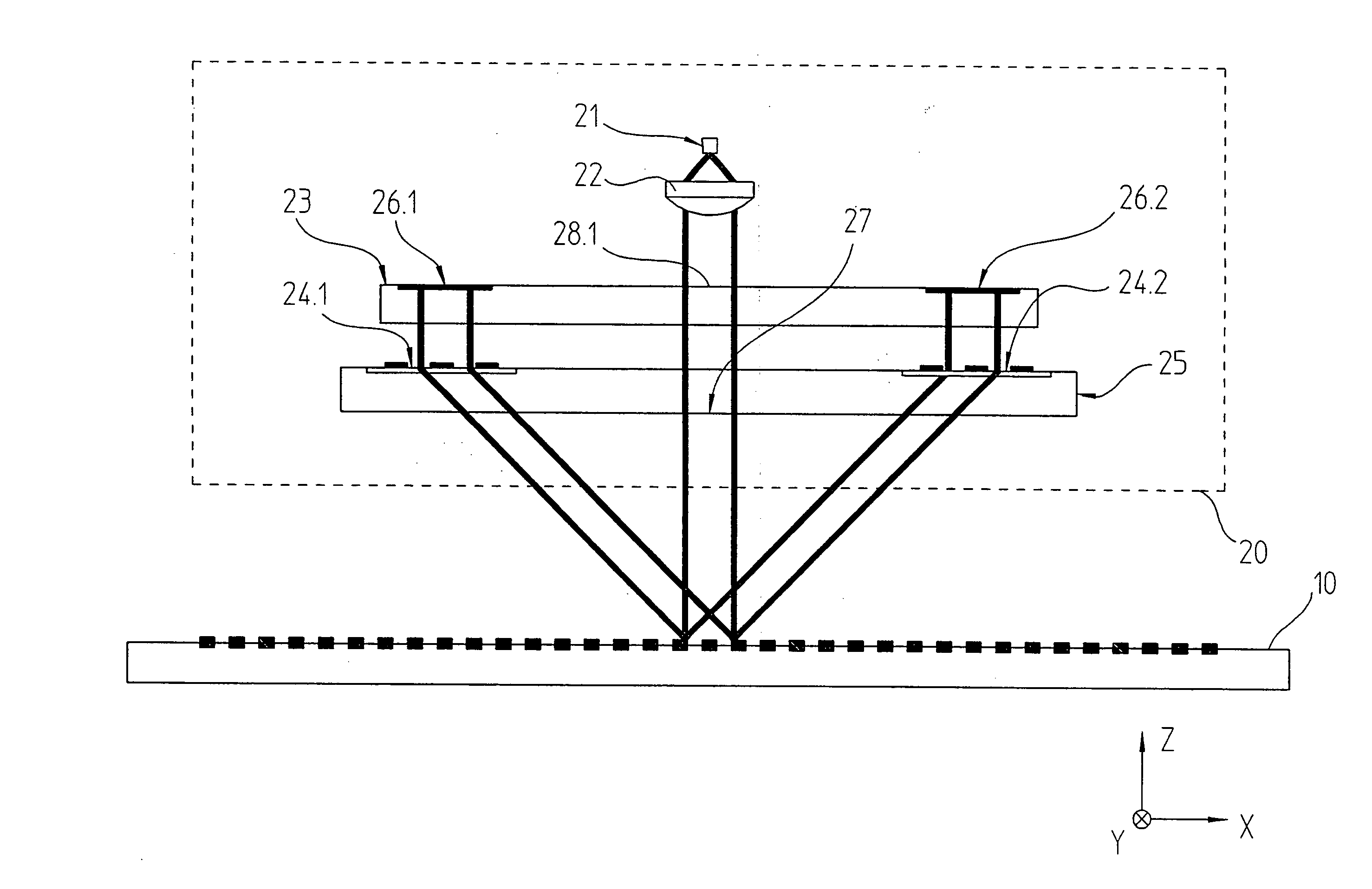
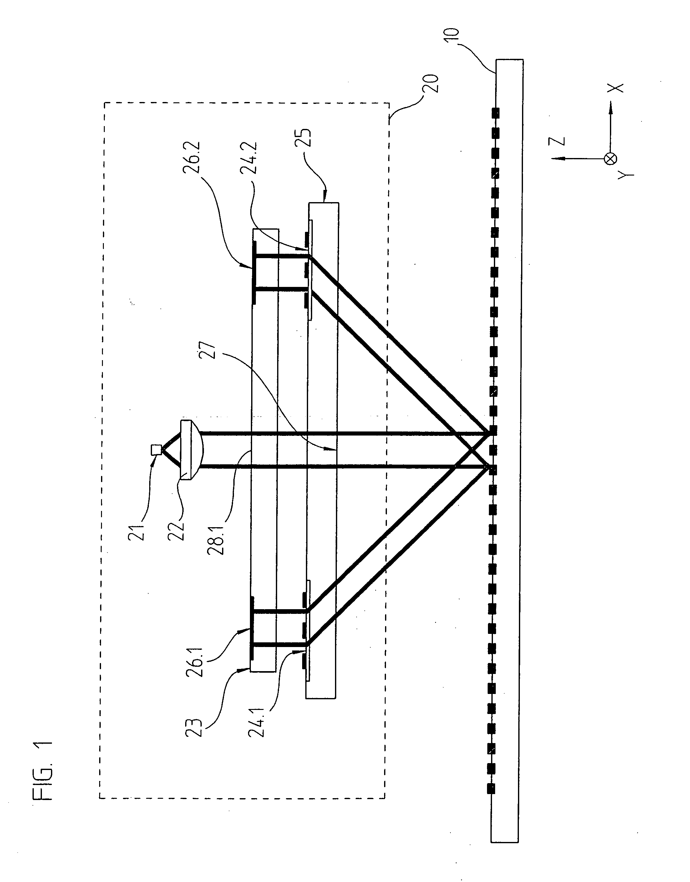
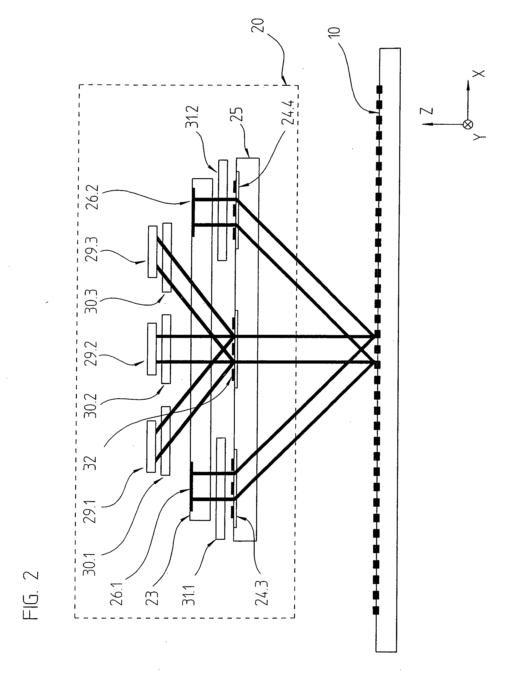
[0055] Referring to FIGS. 1 to 5, a position-measuring device according to an example embodiment of the present invention is arranged as an incident light system. In this connection, FIGS. 1 and 2 each schematically illustrate partial scanning beam paths in a lateral view in the x-z plane, while FIG. 3 is a view of the scanning beam path in the y-z plane. In FIG. 1, the scanning beam-path is illustrated from-light source 21 to reflector elements 26.1 and 26.2, FIG. 2 illustrates the scanning beam path from reflector elements 26.1 and 26.2 to detector elements 29.1, 29.2, 29.3 of the optoelectronic detector system. FIGS. 4 and 5 respectively are top views onto scanning plate 25 or reflector plate 23 that have the optical elements provided there.

[0056] The position-measuring device includes a measuring graduation 10 and a scanning device 20 that is movable with respect to it in at least one measuring direction x. The objects, whose relative position is to be determined with the aid o...


PUM


Abstract

In a position-measuring device for recording the relative position of a scanning unit and a measuring graduation that is movable with respect to the latter in at least one measuring direction, the scanning unit includes a plurality of grating structures as well as at least one reflector element. The elements in the scanning unit are arranged such that the beams of rays diffracted by the measuring graduation pass through first grating structures in the scanning unit, subsequently impinge on the reflector element, from which there takes place a retroreflection in the direction of the measuring graduation, and the partial beams of rays then pass through second grating structures and then once again impinge upon the measuring graduation. The first and the second grating structures are arranged such that, upon the first and second passing through of the partial beams of rays, a defined lens effect on the partial beams of rays results.

Description

CROSS-REFERENCE TO RELATED APPLICATIONS [0001] The present application claims priority to Application No. 10 2005 029 917.2, filed in the Federal Republic of Germany on Jun. 28, 2005, which is expressly incorporated herein in its entirety by reference thereto. FIELD OF THE INVENTION [0002] The present invention relates to a position-measuring device. BACKGROUND INFORMATION [0003] Position-measuring devices are described in PCT International Published Patent Application No. WO 02 / 23131, for example. Besides a measuring graduation, developed, for example, as a linear incident light scale, it includes a scanning unit that is displaceable with respect to it in at least one measuring direction. On the side of the scanning unit, besides a scanning grating, several optoelectronic detector elements, among other things, there is arranged also at least one optical reflector element in the form of a retroreflector. A back reflection takes place via the retroreflector of the partial beam of ray...

Claims


Application Information

Patent Timeline
Patent Type & Authority Applications(United States)
IPC IPC(8): G01B11/14
CPCG01D5/38G01D5/34715
Inventor HOLZAPFEL, WOLFGANG
Owner DR JOHANNES HEIDENHAIN GMBH
Why Eureka
Try Eureka