Zoom lens and image pickup apparatus

a technology of zoom lens and image pickup, which is applied in the direction of mountings, instruments, camera body details, etc., can solve the problems of difficult to adjust the power variation, the influence of the driving mechanism, and the likely presence of the second lens group or the fourth lens group, so as to improve the overall lens length, improve the quality of the overall lens, and reduce the overall lens length

Inactive Publication Date: 2007-01-18
SONY CORP
View PDF2 Cites 11 Cited by
  • Summary
  • Abstract
  • Description
  • Claims
  • Application Information

AI Technical Summary

Benefits of technology

[0030] In the image pickup apparatus, since it includes the zoom lens of the present invention described above, hand shake correction can be performed while the image pickup apparatus is formed in a small size. Further, upon hand shake correction, an out-of-focus state little occurs, and consequently, an image of high quality can be obtained.
[0031] The image pickup apparatus may be configured such that the power variation section includes a first lens group having a positive refracting power, a second lens group having a negative refracting power and a third lens group having a positive refracting power, disposed in order from the object side, and when the lens position state varies from the wide angle end state to the telephoto end state, the distance between the first lens group and the second lens group increases while the distance between the second lens group and the third lens group decreases, the zoom lens further including an aperture stop disposed in the proximity of the third lens group. With the image pickup apparatus, further reduction of the overall lens length can be anticipated, and the variation of off-axis aberration upon power variation can be corrected favorably.
[0032] Preferably, the image pickup apparatus further includes a hand shake detection section for detecting a shake of the image pickup element, a hand shake control section for calculating a blur correction angle for correcting an image blur by the shake of the image pickup element detected by the hand shake detection section and signaling a driving signal for positioning the second sub group at a position based on the blur correction angle, and a hand shake driving section for receiving the driving signal signaled from the hand shake control section and shifting the second sub group in a direction perpendicular to the optical axis based on the received driving signal. With the image pickup apparatus, an image of high quality is acquired whose blur caused by a shake of the image pickup element by a hand shake or the like is corrected and whose various aberrations are corrected favorably while the image is taken up in a well-focused condition.

Problems solved by technology

The arrangement of the shift lens group gives rise to a problem that interference of a driving mechanism for shifting the shift lens group with a mechanism for driving the aperture stop or with a mechanism for driving a lens group which is movable in the direction of the optical axis such as the second lens group or the fourth lens group is likely to occur.
This complicates the structure of a housing and disturbs miniaturization of the zoom lens.
The movement of the shift lens group is guided by a mechanical guide mechanism, and if the guide mechanism does not have some play with respect to the shift lens group (frame which supports the shift lens group), then the movement of the shift lens group is impossible.
This makes the tolerance in manufacture severe, increases the cost and, under certain circumstances, makes production impossible.

Method used


Image

  • Zoom lens and image pickup apparatus
  • Zoom lens and image pickup apparatus
  • Zoom lens and image pickup apparatus

Examples


first embodiment

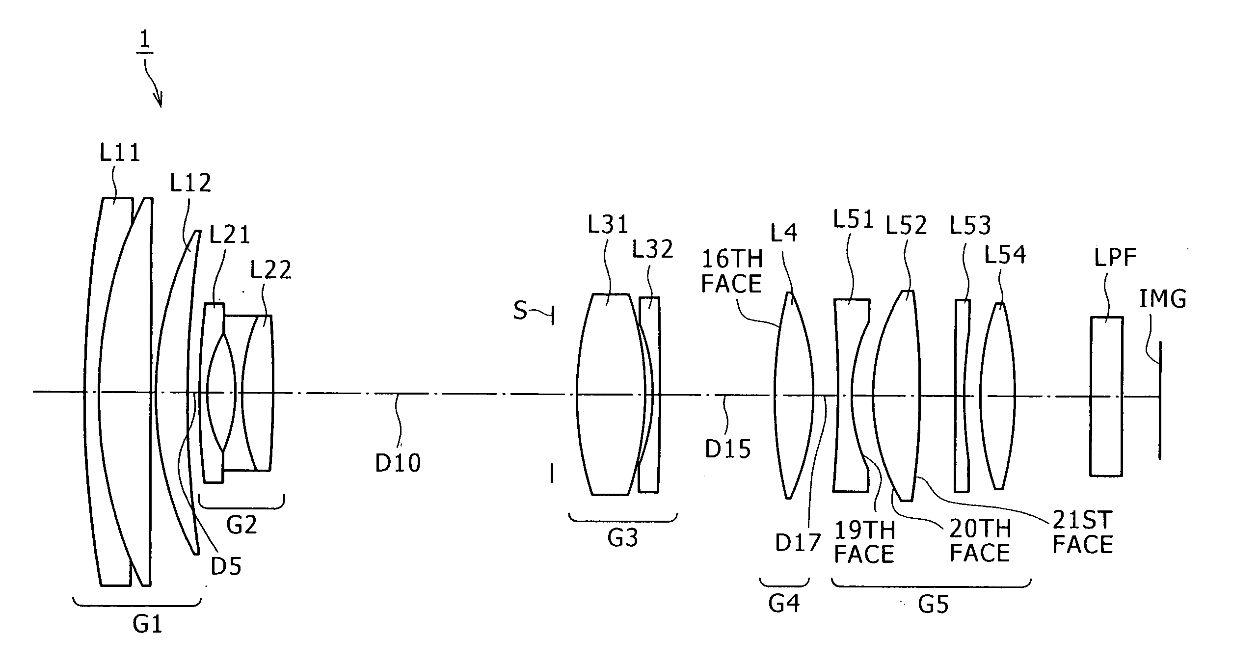
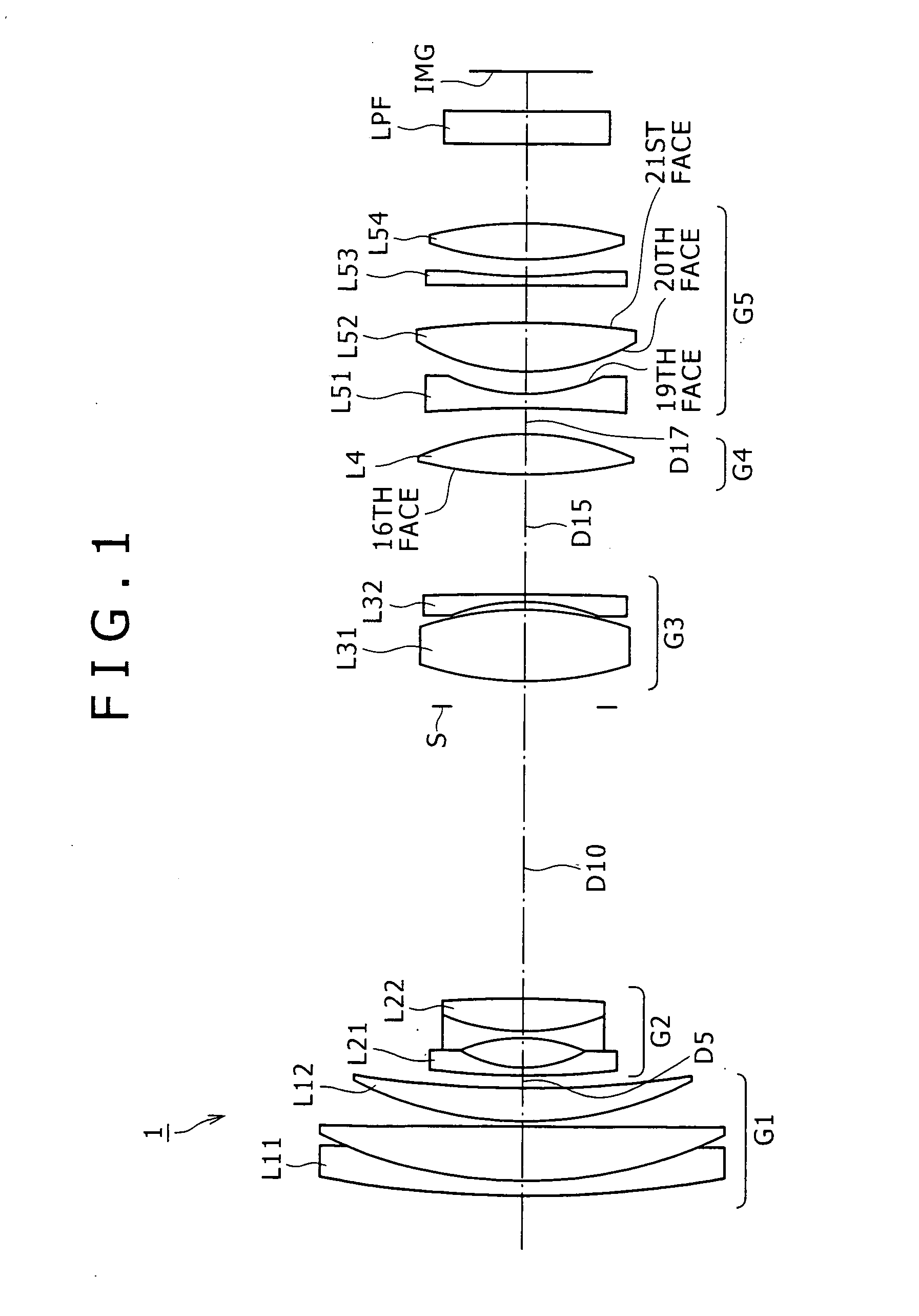
[0112]FIG. 1 illustrates a lens configuration of the zoom lens according to the present invention is applied. Referring to FIG. 1, the zoom lens 1 includes a first lens group G1 having a positive refracting power, a second lens group G2 having a negative refracting power, a third lens group G3 having a positive refracting power, a fourth lens group G4 having a positive refracting power and a fifth lens group G5 having a positive refracting power, disposed in order from the object side. Upon power variation from a wide angle end state to a telephoto end state, the second lens group G2 moves to the image side such that the air distance between the first lens group G1 and the second lens group G2 increases while the air distance between the second lens group G2 and the third lens group G3 decreases. At this time, the first lens group G1, third lens group G3 and fifth lens group G5 are fixed in the direction of the optical axis, and the fourth lens group G4 moves so as to correct the va...

second embodiment

[0123]FIG. 8 illustrates a lens configuration of the zoom lens according to the present invention is applied. Referring to FIG. 8, the zoom lens 2 includes a first lens group G1 having a positive refracting power, a second lens group G2 having a negative refracting power, a third lens group G3 having a positive refracting power, a fourth lens group G4 having a positive refracting power-and a fifth lens group G5 having a positive refracting power, disposed in order from the object side. Upon power variation from a wide angle end state to a telephoto end state, the second lens group G2 moves to the image side such that the air distance between the first lens group G1 and the second lens group G2 increases while the air distance between the second lens group G2 and the third lens group G3 decreases. At this time, the first lens group G1, third lens group G3 and fifth lens group G5 are fixed in the direction of the optical axis, and the fourth lens group G4 moves so as to correct the va...

third embodiment

[0134]FIG. 15 illustrates a lens configuration of the zoom lens according to the present invention is applied. Referring to FIG. 15, the zoom lens 3 includes a first-lens group G1 having a positive refracting power, a second lens group G2 having a negative refracting power, a third lens group G3 having a positive refracting power, a fourth lens group G4 having a positive refracting power and a fifth lens group G5 having a positive refracting power, disposed in order from the object side. Upon power variation from a wide angle end state to a telephoto end state, the second lens group G2 moves to the image side such that the air distance between the first lens group G1 and the second lens group G2 increases while the air distance between the second lens group G2 and the third lens group G3 decreases. At this time, the first lens group G1, third lens group G3 and fifth lens group G5 are fixed in the direction of the optical axis, and the fourth lens group G4 moves so as to correct the ...


PUM


Abstract

A zoom lens wherein the image plane movement upon lens shifting is minimized. A power variation section and a final lens group are disposed in order from an object side. The power variation section includes at least two lens groups movable in an optical axis direction to vary a lens position state. The final lens group is fixed in the optical axis direction and includes first to third sub groups having negative, positive and positive refracting powers and disposed in order from the object side. The second sub group is shiftable substantially perpendicularly to the optical axis to shift an image. A conditional expression 0.2<ft/fBt<0.8 is satisfied where ft and fBt are the focal distances of the lens system and entire lens groups disposed on the object side of the third sub group in the telephoto end state.

Description

CROSS REFERENCES TO RELATED APPLICATIONS [0001] The present invention contains subject matter related to Japanese Patent Application JP 2005-153624 filed with the Japanese Patent Office on May 26, 2005, the entire contents of which being incorporated herein by reference. BACKGROUND OF THE INVENTION [0002] This invention relates to a novel zoom lens and image pickup apparatus, and more particularly to a zoom lens and an image pickup apparatus suitable for use with a camera such as a video camera or a digital still camera wherein an image pickup device is used to receive light to pick up an image. [0003] Zoom lenses of various zoom types are in the past used for video cameras. [0004] One of such zoom lenses as mentioned above is disclosed, for example, in Japanese Patent Laid-open No. 2000-121938 (hereinafter referred to as Patent Document 1). The zoom lens disclosed in Patent document 1 adopts a five-group configuration having positive, negative, positive, positive and negative lens ...

Claims


Application Information

Patent Timeline
Patent Type & Authority Applications(United States)
IPC IPC(8): G02B15/14
CPCG02B27/646G02B15/173G02B15/145113
Inventor OTAKE, MOTOYUKI
Owner SONY CORP
Why Eureka
Try Eureka