Unlock instant, AI-driven research and patent intelligence for your innovation.

Method and system for determining location of phase-to-earth fault

a phase-to-earth fault and fault technology, applied in the direction of fault location by conductor type, emergency protective arrangement for limiting excess voltage/current, instruments, etc., can solve the problem of large error in fault location estimation, inability to accurately determine the location of the fault, and computational burden on the solution. problem, to achieve the effect of increasing the computational capacity

Active Publication Date: 2007-01-18
ABB (SCHWEIZ) AG
View PDF5 Cites 11 Cited by
  • Summary
  • Abstract
  • Description
  • Claims
  • Application Information

AI Technical Summary

Benefits of technology

[0031] An advantage of the method and system of the invention is that an estimate for a location of a phase-to-earth fault can be determined accurately also on non-homogeneous lines without substantially increasing the computational capacity required.

Problems solved by technology

This means that electrically the feeder is non-homogeneous.
However, while distribution lines are in most cases non-homogeneous, the impedance algorithms applied in protective relays typically do not take this into account, which may cause a considerable error in a fault location estimate.
The solution, however, is computationally rather burdensome as e.g. individual loads on the feeder are taken into account.
This solution is also computationally burdensome and thus difficult to implement in a protective relay.

Method used


Image

  • Method and system for determining location of phase-to-earth fault
  • Method and system for determining location of phase-to-earth fault
  • Method and system for determining location of phase-to-earth fault

Examples


Embodiment Construction

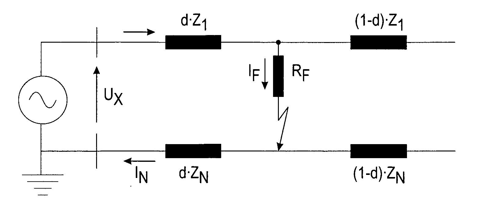
[0037] A use of the method and system of the invention is not limited to any specific system, but they can be used in connection with various three-phase electric systems to determine a location of a phase-to-earth fault in a three-phase electric line of an electric network. The electric line can be a feeder, for example. The electric network can be an electric transmission or distribution network or a component thereof, for example. Moreover, the use of the invention is not limited to systems employing 50 Hz or 60 Hz fundamental frequencies or to any specific voltage level.

[0038]FIG. 2 is a diagram illustrating an electric network to which the invention can be applied. The figure only shows the components necessary for understanding the invention. The exemplary network can be a medium voltage (e.g. 20 kV) distribution network fed through a substation comprising a transformer 10 and a busbar 20. The figure further shows an electric line outlet, i.e. a feeder 30 which consists of th...


PUM


Abstract

A method and system for determining a location of a phase-to-earth fault in a line of an electric network, the electric line comprising two or more sections (30a, 30b, 30c), the system being configured to determine, at a measuring point, a reactance of a fault loop; determine a faulted section of the electric line to be a section closest to the measurement point of all such sections for which a sum of a positive sequence reactance and an earth return path reactance of the section in question and positive sequence reactances and an earth return path reactances of sections, if any, between the measurement point and the section in question is greater than or equal to the determined reactance of the fault loop; and calculate a distance between the measuring point and a point of fault on the basis of the reactance values.

Description

[0001] The present application claims priority under 35 USC §119 to Finnish Patent Application No. 20055359 filed Jun. 29, 2005, the contents of which are hereby incorporated by reference in their entirety. FIELD OF THE INVENTION [0002] The present invention relates to localization of earth faults in electric networks. BACKGROUND OF THE INVENTION [0003] A feeder of a distribution network typically consists of many different types of over-headline and / or cable sections. This means that electrically the feeder is non-homogeneous. [0004] Conductor parameters (resistance, inductance and capacitance) can vary greatly, depending on conductor type and configuration. Especially overhead-line and cable parameters differ from each other. Typically, the angle of the positive sequence impedance on cables is substantially less than on overhead-lines. Also different overhead-line types differ from each other. The same applies to cables. [0005] Inherently, the result of an impedance based fault lo...

Claims


Application Information

Patent Timeline
IPC IPC(8): H02H3/00G01RG01R31/08
CPCG01R31/088G01R31/086
Inventor ALTONEN, JANNEWAHLROOS, ARI
Owner ABB (SCHWEIZ) AG