
Circuits and methods for a multi-differential embedded-clock channel

a multi-differential embedded clock and circuit technology, applied in the field of data communication channels, can solve the problems of limiting the propagation time of global clock, and limiting the bandwidth of data transfer by bus

Active Publication Date: 2007-01-18
MCGEE JAMES RIDENOUR
View PDF23 Cites 15 Cited by
  • Summary
  • Abstract
  • Description
  • Claims
  • Application Information

AI Technical Summary

Problems solved by technology

Because the next value driven to the bus takes some time to propagate from the sources to the destination, the period of the global clock can be limited by the propagation times between the sources and the destinations.
This limitation on the clock period can limit the bandwidth of data transfer by the bus.
However, the differences in propagation times, or skew, between the source-synchronous clock and each data bit of the bus can limit the bandwidth of data transfer by the bus.
The skew can be reduced by transmitting multiple copies of the source-synchronous clock for various subsets of the data bits of the bus; however, each source-synchronous clock adds overhead that reduces the effective bandwidth per signal of the bus.
However, the jitter of the transmit clock and the recovered clock may misalign the sampling of the data at the destination and thereby limit the bandwidth of data transfer by the channel.
For example, phase-locked loops are specialized analog circuits that are expensive and time-consuming to design, occupy a significant amount of area on an integrated circuit, and dissipate a significant amount of power during operation.
The scaling of generations of integrated circuit fabrication processes is making the design of these specialized analog circuits more expensive and more time-consuming.
Even with these special transistors supporting a higher power supply voltage, the design of analog circuits is becoming more difficult and time-consuming with each process generation.

Method used


Image

  • Circuits and methods for a multi-differential embedded-clock channel
  • Circuits and methods for a multi-differential embedded-clock channel
  • Circuits and methods for a multi-differential embedded-clock channel

Examples


Embodiment Construction

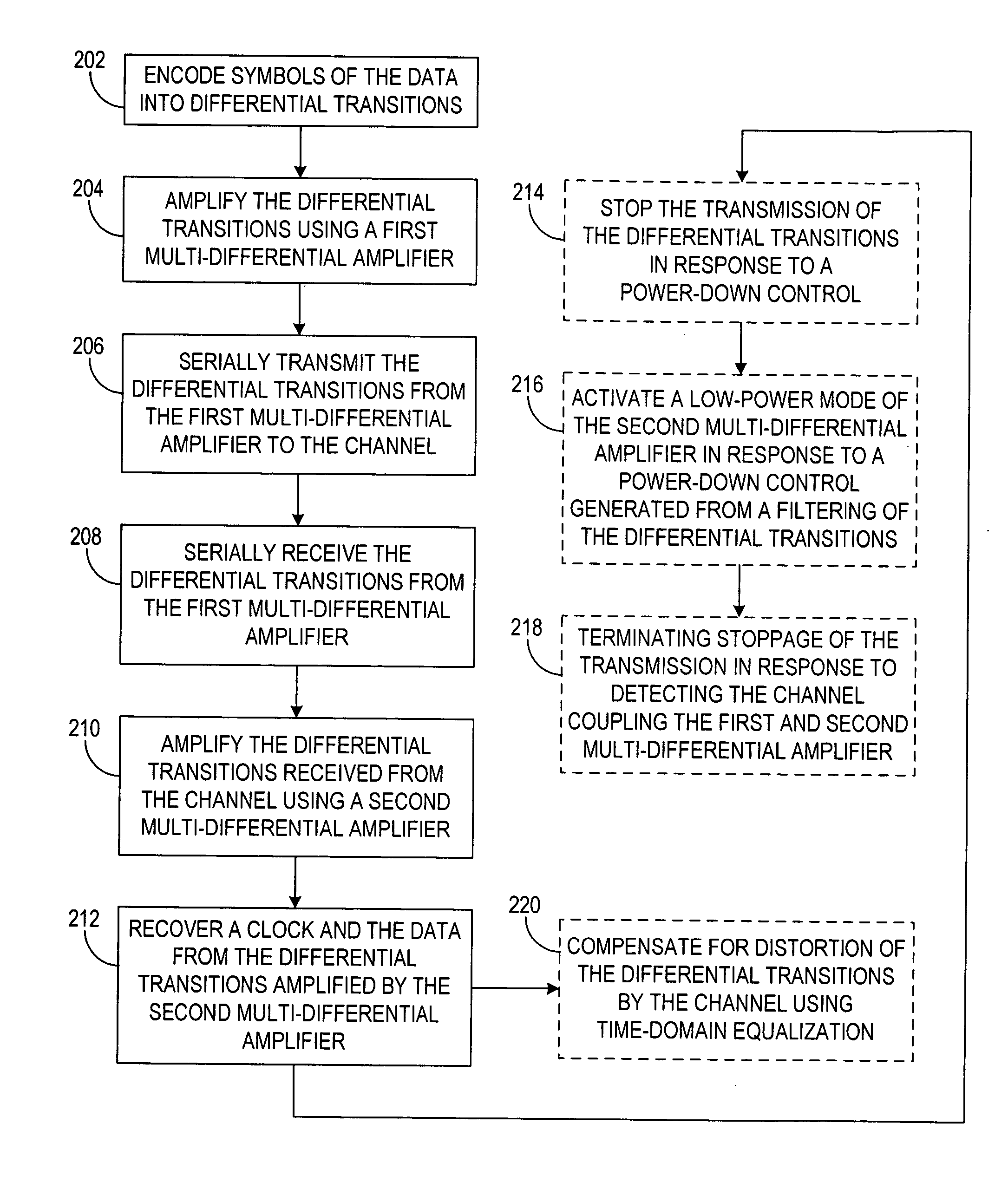
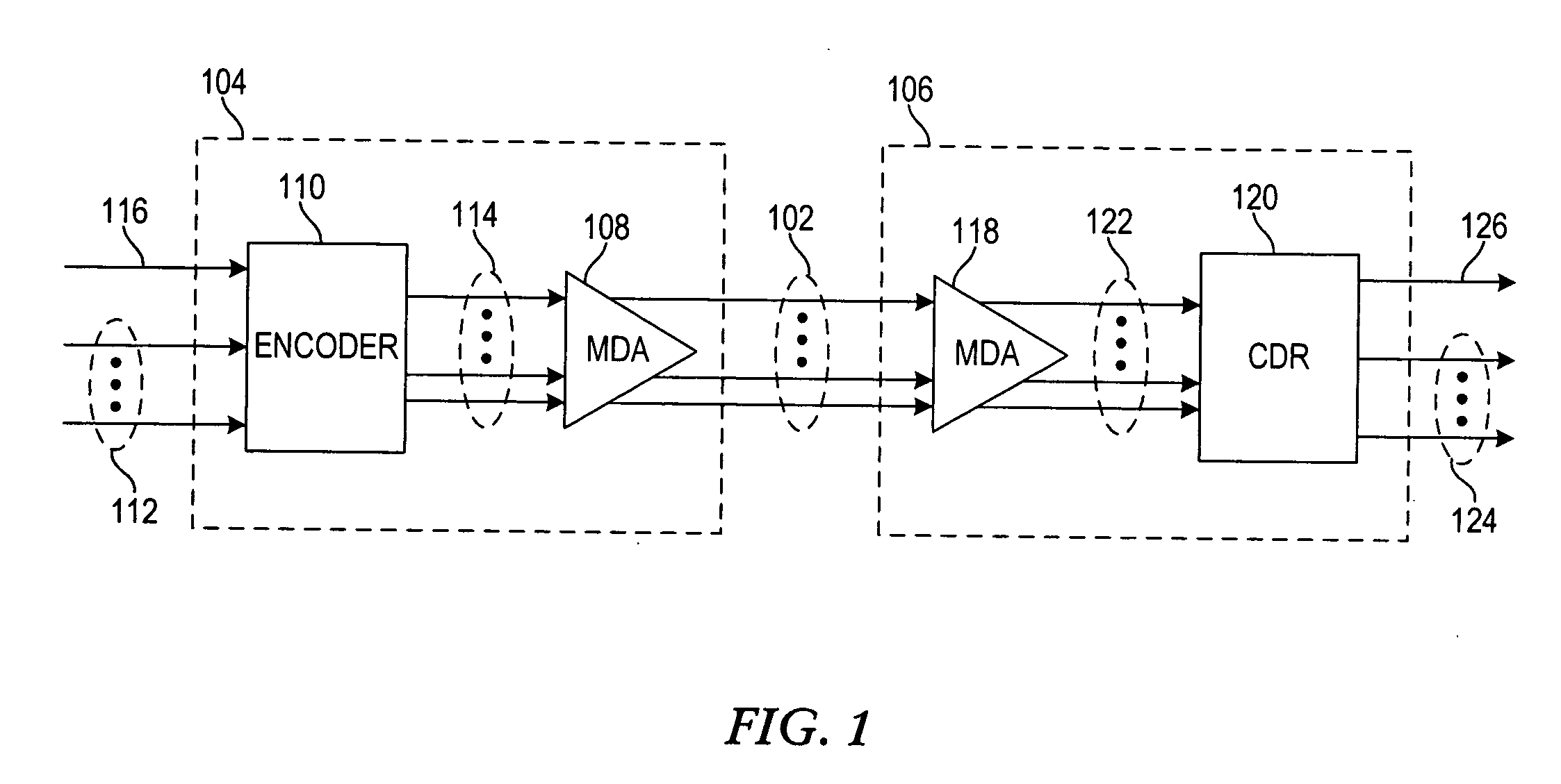
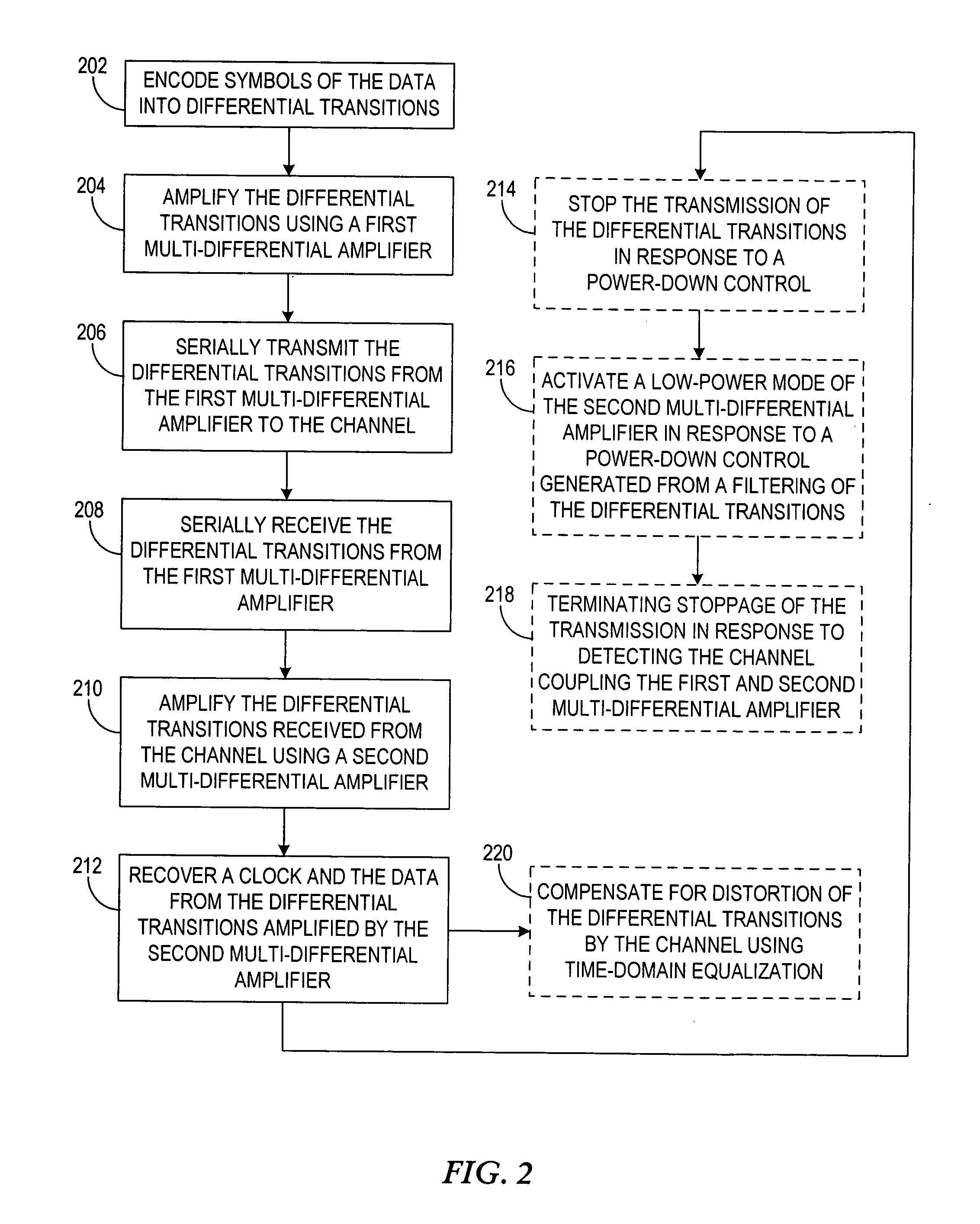
[0016] Various embodiments of the invention use multi-differential signaling to communicate data from a transmitter to a receiver through a channel that has at least four signals. For each symbol of the data, the signals of the channel have a corresponding differential transition. Because each of the differential transitions communicating the data can be a differential transition between any two signals of the channel, the signaling is denoted multi-differential signaling. The differential transitions are serially communicated through the channel, such that the differential transitions nominally occur one at a time. Further, there is a differential transition for every symbol, such that a clock is embedded in the differential transitions. In contrast with an existing encoded-clock signaling using the 8b / 10b encoding, various embodiments of the invention provide embedded-clock signaling for which the clock can be recovered without using a phase-locked-loop.

[0017] For further discuss...


PUM


Abstract

An interface circuit for a multi-differential embedded-clock channel for communicating data provides efficient utilization of the bandwidth of the channel. The interface circuit includes at least four first signals, at least four second signals, and a multi-differential amplifier. The multi-differential amplifier is coupled to the first and second signals. The multi-differential amplifier is adapted to generate the second signals by amplifying, for all combinations of two of the first signals, differential transitions between the two of the first signals. Each of a plurality of symbols of the data has a corresponding one of the differential transitions, and the differential transitions are serially communicated through the channel.

Description

FIELD OF THE INVENTION [0001] The present invention generally relates to data communication channels. BACKGROUND [0002] Data can be communicated between computers and within computers using various protocols for communicating the data. Data can be synchronously communicated using a global clock that is provided to both the sources and the destinations of the data. Each destination can sample the current value from a bus connecting the sources and the destinations at transitions of the global clock and each source can transmit the next value to the bus at these transitions of the global clock. Because the next value driven to the bus takes some time to propagate from the sources to the destination, the period of the global clock can be limited by the propagation times between the sources and the destinations. This limitation on the clock period can limit the bandwidth of data transfer by the bus. [0003] Data may also be synchronously communicated using a source-synchronous clock. A s...

Claims


Application Information

Patent Timeline
IPC IPC(8): H04L5/16H04L25/00
CPCH04W52/0235H04L25/0272Y10S388/91Y02D30/70
Inventor MCGEE, JAMES RIDENOUR
Owner MCGEE JAMES RIDENOUR
Learn More