Video coding method and apparatus for reducing mismatch between encoder and decoder

a video coding and encoder technology, applied in the field of video coding technology, can solve the problems of mismatch of reference frames, inability to predict, and inability to meet the requirements of the target frame, so as to improve the video compression efficiency and reduce the drift error

Inactive Publication Date: 2007-01-18
SAMSUNG ELECTRONICS CO LTD
View PDF2 Cites 18 Cited by
  • Summary
  • Abstract
  • Description
  • Claims
  • Application Information

AI Technical Summary

Benefits of technology

[0021] Accordingly, an aspect of the present invention is to provide an apparatus and method capable of improving the video compression efficiency by reducing the drift error between an encoder and a decoder in an MCTF video codec.
[0022] Another aspect of the present invention is to provide an apparatus and method capable of effectively re-estimating a high-pass frame in an MCTF video codec.

Problems solved by technology

Since the existing text-based communication systems are insufficient to meet diverse needs of consumers, multimedia services that can deliver various types of information including texts, images, music, and others, are increasing.
These multimedia services typically require a storage medium having a large capacity to store a massive amount of multimedia data.
On the other hand, the open-loop structure has an error drift problem, which results from the mismatch of reference frames between the encoder and the decoder.
However, although the amount of error drift may decrease through the update step, the mismatch between the encoder and the decoder still remains in the open-loop structure, such that the performance is inevitably degraded.
The first is the mismatch in the prediction step.
However, since the left and right reference frames are not quantized, the H frame derived from the left and right reference frames may not be an optimum signal in the decoder side.
However, since the left and right reference frames must be transformed through the update step and transformed into the H frames in the next temporal level so as to be quantized, it is difficult to previously quantize the reference frames if the MCTF structure has an open-loop structure, rather than a closed-loop structure.
However, since the high-pass frame has not been yet quantized, the mismatch may occur between the encoder and the decoder.

Method used


Image

  • Video coding method and apparatus for reducing mismatch between encoder and decoder
  • Video coding method and apparatus for reducing mismatch between encoder and decoder
  • Video coding method and apparatus for reducing mismatch between encoder and decoder

Examples


Embodiment Construction

[0040] Hereinafter, exemplary embodiments of the present invention will be described with reference to the accompanying drawings. The matters defined in the description such as a detailed construction and elements are provided to assist in a comprehensive understanding of the invention. Thus, it should be apparent that the present invention can be carried out without those defined matter. In the following description of the present invention and in the drawings, the same reference numerals are used for the same elements. Also, a detailed description of known functions and configurations incorporated herein will be omitted.

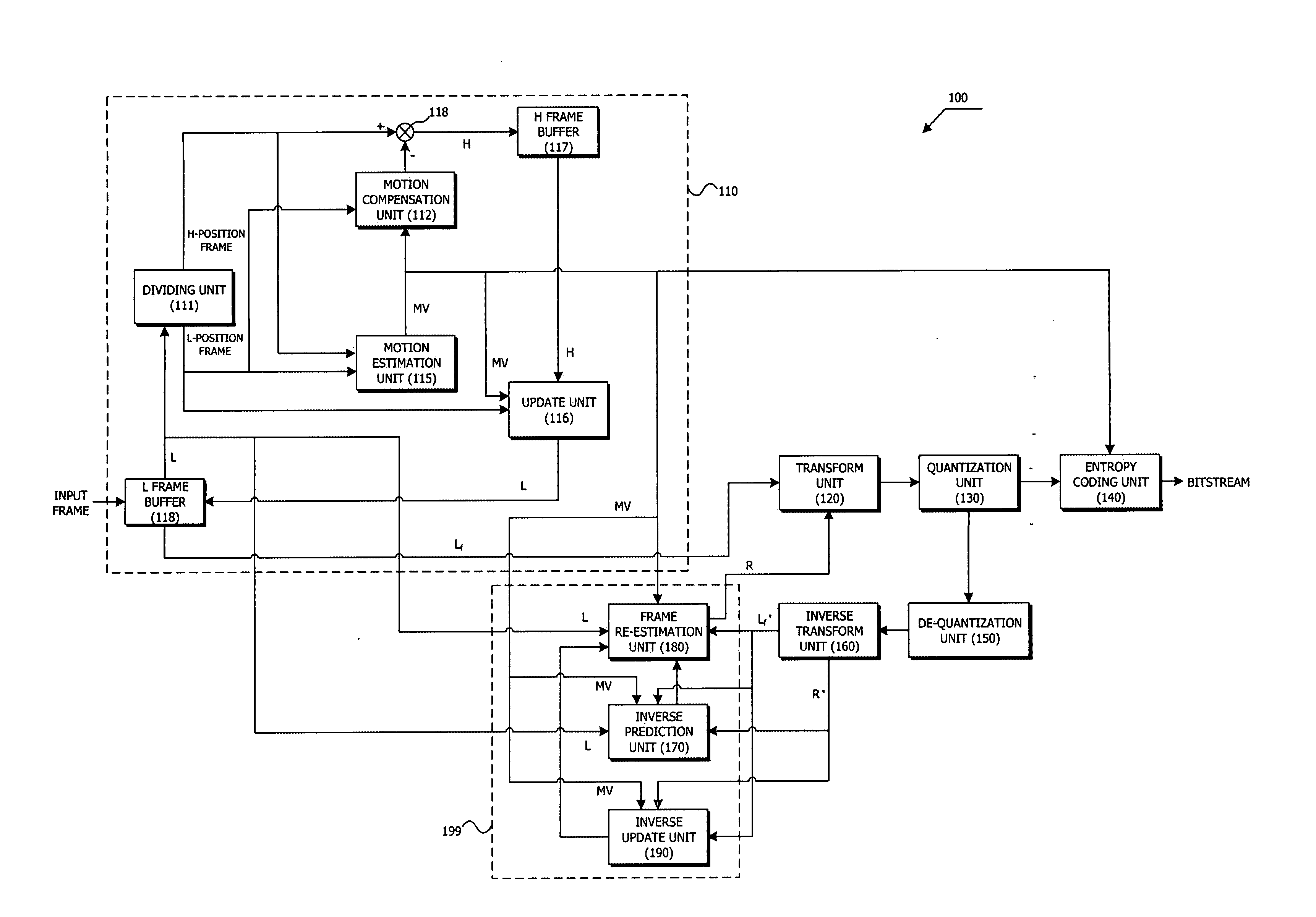
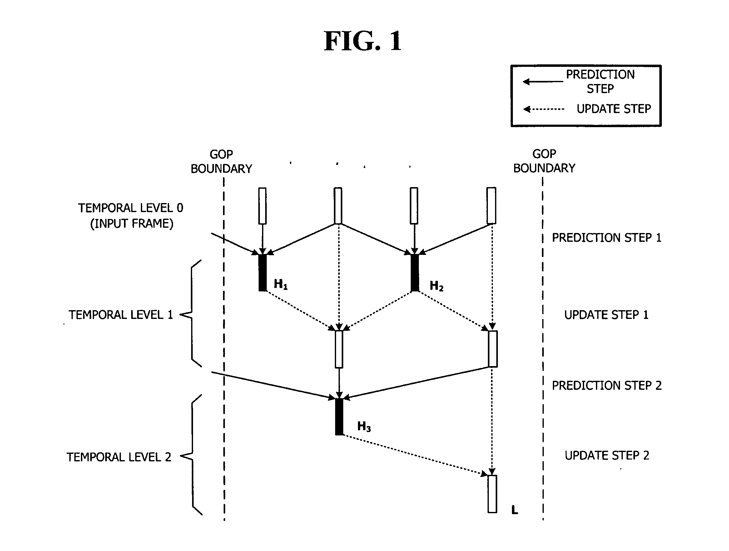
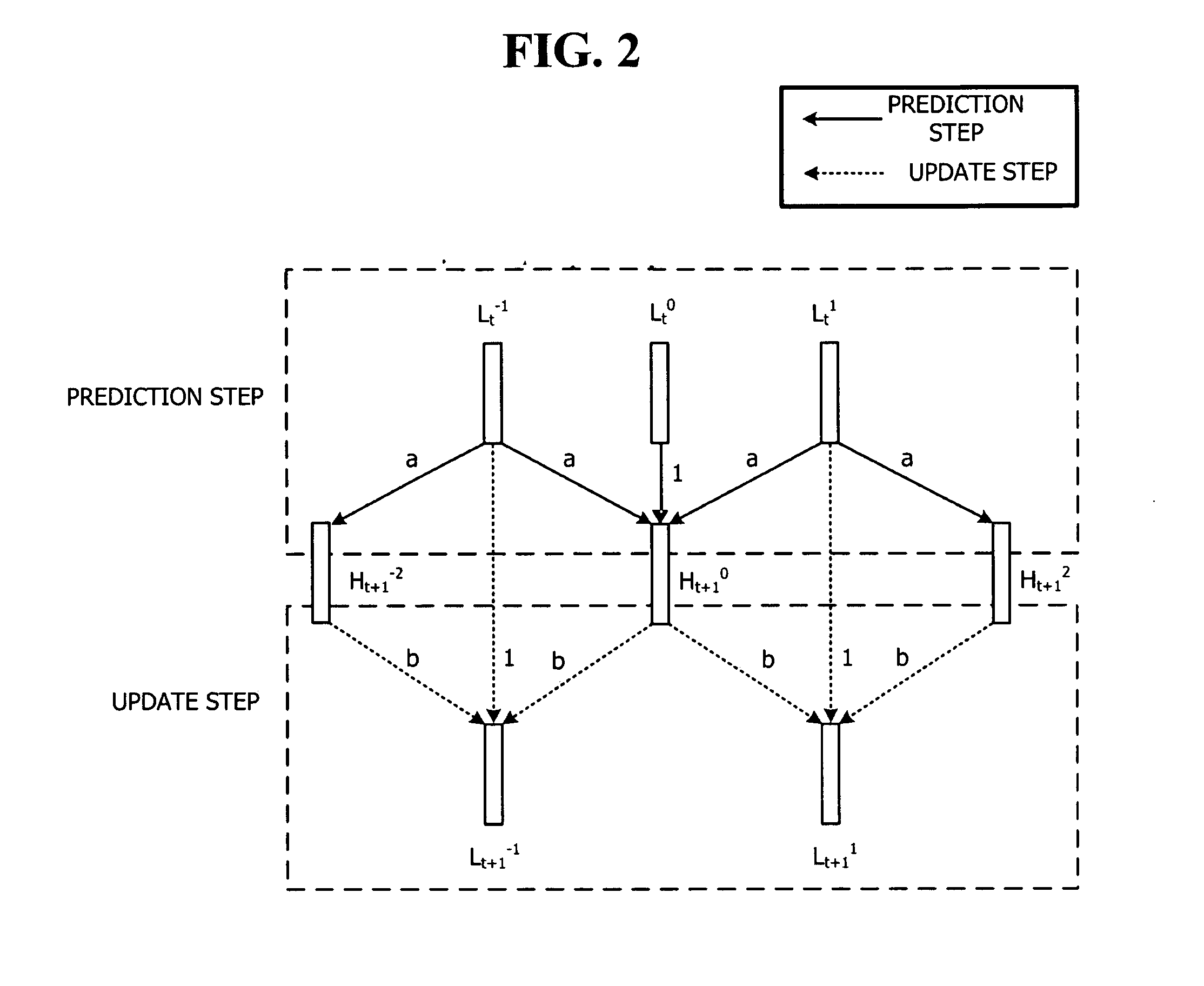
[0041] The present invention provides a method of reducing the mismatch in the prediction step by re-estimating the H frame during the coding / decoding processes after the MCTF process (hereinafter, this process will be referred to as a “frame re-estimation process”). In addition, the present invention will be described with reference to exemplary embodiments, in w...


PUM


Abstract

A method of reducing mismatch between an encoder and a decoder in a motion compensated temporal filtering process and a video coding method and apparatus using the same. The video coding method includes the steps of dividing input frames into one final low-pass frame and at least one high-pass frame through a motion compensated temporal filtering, coding the final low-pass frame and then decoding the coded final low-pass frame, re-estimating the high-pass frame by using the decoded final low-pass frame, and coding the re-estimation high-pass frame.

Description

CROSS-REFERENCE TO RELATED APPLICATIONS [0001] This application claims priority from Korean Patent Application No. 10-2005-0088921 filed on Sep. 23, 2005, and U.S. Provisional Patent Application Nos. 60 / 699,859 and 60 / 700,330 filed on Jul. 18, 2005 and Jul. 19, 2005, respectively, the whole disclosures of which are hereby incorporated herein by reference.BACKGROUND OF THE INVENTION [0002] 1. Field of the invention [0003] Apparatuses and methods consistent with the present invention relate to a video coding technology, and more particularly to reducing mismatch between an encoder and a decoder in a motion compensated temporal filtering (MCTF) process. [0004] 2. Description of the Prior Art [0005] Recently, with the advancements in information and communication technologies including the Internet, widespread use of multimedia communications is rapidly increasing along with text and voice communications. Since the existing text-based communication systems are insufficient to meet diver...

Claims


Application Information

Patent Timeline
Patent Type & Authority Applications(United States)
IPC IPC(8): H04N7/12H04B1/66
CPCH04N19/13H04N19/63H04N19/615H04N19/53H04N19/61H04N19/51
Inventor HAN, WOO-JINLEE, BAE-KEUN
Owner SAMSUNG ELECTRONICS CO LTD
Why Eureka
Try Eureka