Modular broadband bi-directional programmable switch with hot-swappable modules

a module and module technology, applied in the field of modular switching apparatus, can solve the problems of preventing the repair of failed modules, complicated construction of switches disclosed in singers, and affecting the operation of electrical signals, so as to minimize signal loss and minimize trace length

Inactive Publication Date: 2007-01-18
QUINTECH ELECTRONICS & COMM
View PDF14 Cites 20 Cited by
  • Summary
  • Abstract
  • Description
  • Claims
  • Application Information

AI Technical Summary

Benefits of technology

[0006] The next generation modular switch has design enhancements which remedy the deficiencies in the current state of the art modular switch. The switch consists of a backplane into which input and output boards are plugged, as well as boards which bridge the input and output boards. This modular design eliminates internal cabling and the layout of the backplane allows the removal and replacement of all boards without disturbing other boards in the system, allowing the hot swappable, in field servicing of the switches. Initial assembly of the units is also greatly simplified, representing a savings in labor costs to assemble the units. Further, the next generation switch disclosed herein also has a high level of redundancy, allowing re-routing of connections in the event of a failure of one or more components, and the capability of self-diagnosis of faulty boards. The new modular design also provides a savings in physical space requirements, allowing a 32×32 switch in a 6U chassis form factor.
[0010] The backplane of the switch is laid out in a unique manner such as to minimize trace length, and thereby minimize signal loss as the signals are routed from the inputs to the outputs. The switch is also configured such that all components (i.e., all input and output cards, as well as the bridging cards, are accessible from the front of the unit and are hot-swappable without the need to disconnect cables or disassemble the units. All cards simply plug into the backplane utilizing standard off the shelf connecting hardware and hardware to secure the cards in place within the chassis. Input and output cards are also keyed to prevent their insertion into the wrong slots.

Problems solved by technology

First, the construction of the switch disclosed in Singer is complicated in that, after the switch matrix is placed in an enclosure, it may be necessary to remove and / or disassemble the entire assembly of modules in order to remove a single module.
This makes the switch labor-intensive to construct and precludes repair of failed modules in the field.
Additionally, it is impossible for an end user to upgrade existing switches (i.e., from 4×4 to 8×8 or 1 6×16) by adding or replacing modules in the field.
Thus, in the event a single module fails in the field, an end user will have to send the entire unit in to the manufacturer for repair or upgrade.
Second, the current switches are physically large in size.
Often, rack space may be limited.

Method used


Image

  • Modular broadband bi-directional programmable switch with hot-swappable modules
  • Modular broadband bi-directional programmable switch with hot-swappable modules
  • Modular broadband bi-directional programmable switch with hot-swappable modules

Examples


Embodiment Construction

[0019] The switch of the current invention solves problems with backplane complexity, number of boards, space required and internal cabling complexity by using a different type of matrix architecture than is known in the prior art in this area. The architecture, known as a Clos or 3-stage matrix, is non-standard in the RF switching art, but is known in the prior art in other segments of the electronics industry. The Clos architecture builds a large matrix from smaller submatrices in a multilayer format.

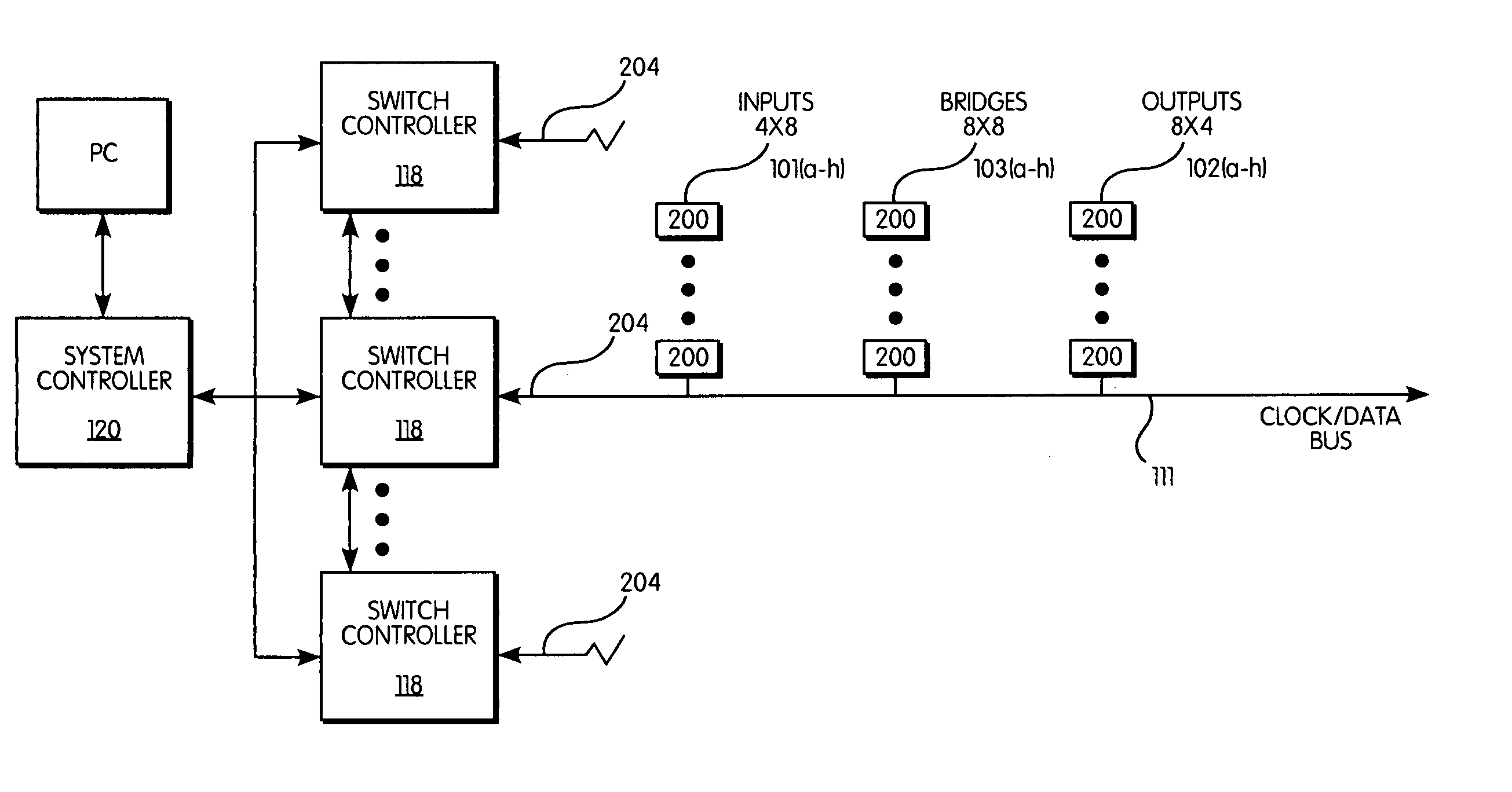
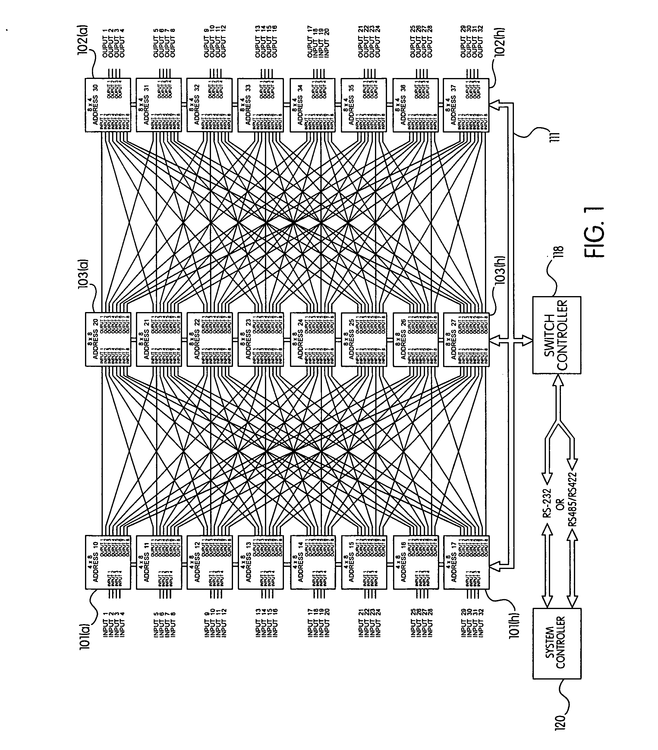
[0020] In the preferred embodiment of the invention, as shown in FIG. 1, there are eight input cards, each having a 4×8 matrix, four bridge cards, each having two 8×8 matrices and eight output cards, each having an 8×4 matrix, with standard splitter switch architecture. The eight input cards, four bridge cards and eight output cards are arranged in a three stage Clos matrix architecture to form a 32×32 switching matrix. The architecture requires only 128 connections between cards as ...


PUM


Abstract

A programmable switch for broadband signals having a modular design in which input cards, bridging cards and output cards are interconnected through a common backplane to form a switching matrix having a Clos architecture. All connections between cards are made through the backplane to decrease the complexity of the switch and are arranged to minimize the length of signal traces to minimize signal loss. The backplane is unique in that it is configured with venting holes to facilitate the flow of cooling air therethrough. All modules, including input cards, output cards and bridge cards are hot swappable.

Description

FIELD OF THE INVENTION [0001] This invention is related to the field of switching of electrical signals, specifically, signals ranging from DC to the gigahertz range, and, in particular, to improvements to a modular switching apparatus. BACKGROUND OF THE INVENTION [0002] The state of the art in the switching of electrical signals, and in particular, signals in the RF frequency range, is currently a modular, programmable switch of the type disclosed in U.S. Pat. No. 5,481,073 (Singer, et al.), which is incorporated herein by reference. This switch is modular, in that it is built from a plurality of identical switching modules, typically having a plurality of inputs / outputs which can be programmatically switched to a single input / output. By physically arranging the modules in a matrix fashion, that is, a plurality of modules stacked in a side-by-side fashion, with a second tiered plurality of modules, also stacked in a side-by-side fashion, a switch having an arbitrary number of input...

Claims


Application Information

Patent Timeline
Patent Type & Authority Applications(United States)
IPC IPC(8): G06F13/00
CPCH04Q1/04H04Q1/10H04Q1/145H04Q1/155H05K7/1459H04Q1/035H04Q2201/12
Inventor PHELPS, THOMAS B.FARICH, MICHAEL L.BAKER, BRADLEY H.
Owner QUINTECH ELECTRONICS & COMM
Why Eureka
Try Eureka