Method and system for finding evolving regions in graphs without persistent node identity

a graph and region technology, applied in the field of information processing system environments, can solve problems such as system crash, memory leakage, and inability to apply techniques in many important runtime environments, and achieve the effect of reducing system overhead

Inactive Publication Date: 2007-01-18
GOOGLE LLC
View PDF1 Cites 31 Cited by
  • Summary
  • Abstract
  • Description
  • Claims
  • Application Information

AI Technical Summary

Benefits of technology

[0014] One advantage of the foregoing embodiments of the present invention is that accurate estimates or patterns of how an environment in a computer system is evolving are created f...

Problems solved by technology

A common challenge when using graphs is identifying subsets of graphs that are growing without bound.
These graph subsets may eventually cause the system to crash when it exceeds available system resources, such as memory.
This problem is known as a memory leak.
However, these techniques cannot be applied in many important runtime environments, for example, Java environments, that have restrictions on data collection and environment analysis.
The limitations of the prior art are especially evident when analyzing deployed programs.
In this setting, there are certain operations that prior art techniques are restricted from performing and many times the assumptions used by the prior art techniques are invalid.
Another common restriction is that the analysis of the program should be performed while the program is executing in its native environment.
When a program is executed in a clean-room setting, reproducing the problems of interest during the program's execution is very difficult or impossible.
These restrictions imply that evolution analysis techniques cannot assume that graph nodes have unique and persistent identities.
However, prior art techniques have carried these assumptions.
These assumptions are difficult to enforce because they impose a large space and time overh...

Method used


Image

  • Method and system for finding evolving regions in graphs without persistent node identity
  • Method and system for finding evolving regions in graphs without persistent node identity
  • Method and system for finding evolving regions in graphs without persistent node identity

Examples


Embodiment Construction

[0046] As required, detailed embodiments of the present invention are disclosed herein; however, it is to be understood that the disclosed embodiments are merely exemplary of the invention, which can be embodied in various forms. Therefore, specific structural and functional details disclosed herein are not to be interpreted as limiting, but merely as a basis for the claims and as a representative basis for teaching one skilled in the art to variously employ the present invention in virtually any appropriately detailed structure. Further, the terms and phrases used herein are not intended to be limiting; but rather, to provide an understandable description of the invention.

[0047] The terms “a” or “an”, as used herein, are defined as one or more than one. The term plurality, as used herein, is defined as two or more than two. The term another, as used herein, is defined as at least a second or more. The terms including and / or having, as used herein, are defined as comprising (i.e., ...


PUM


Abstract

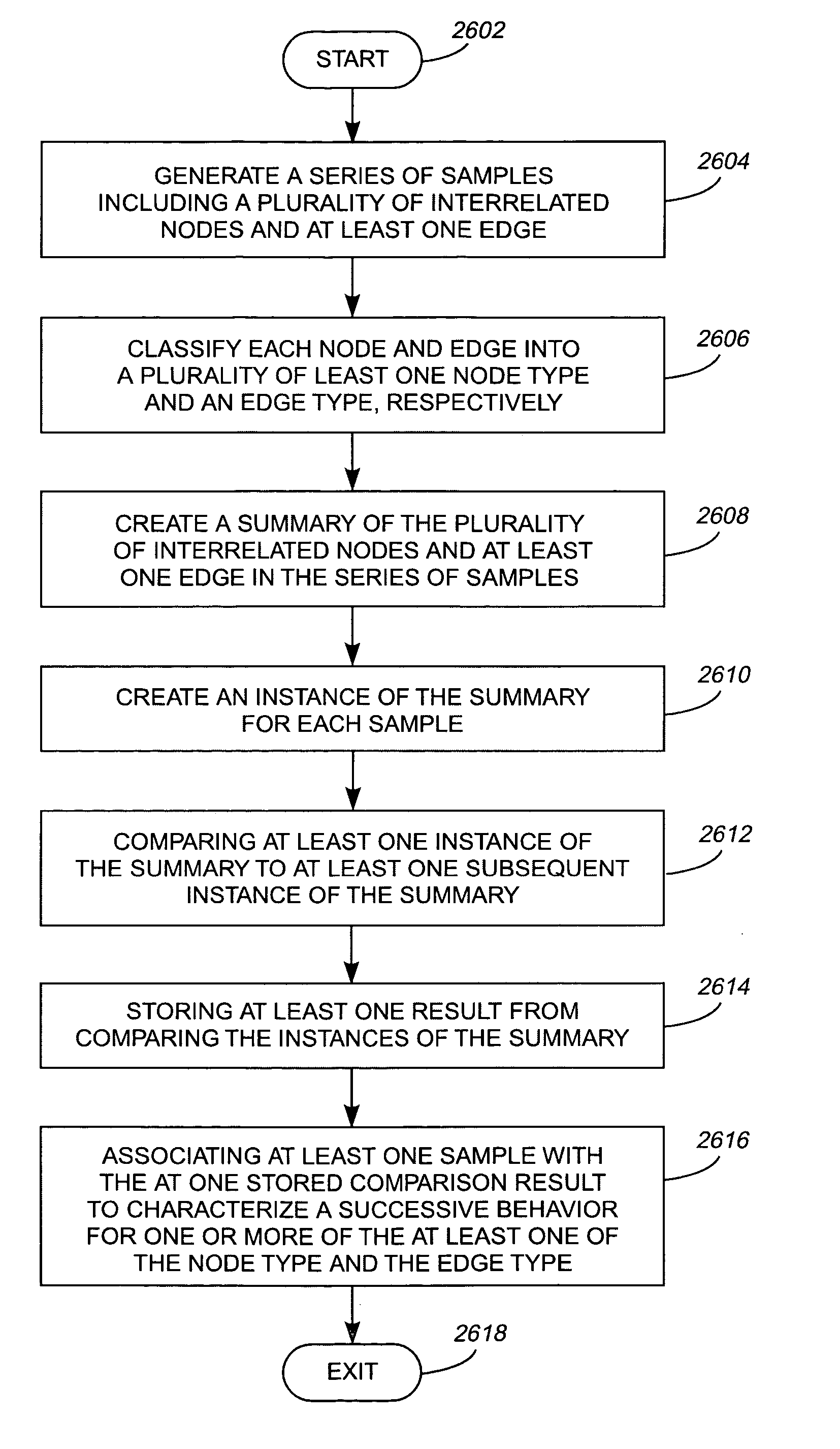
A system, method, and computer program for identifying evolving regions in a graph of interrelated nodes representing a computer system environment. The method includes generating a series of samples (302) of the environment. Each sample includes a plurality of interrelated nodes (502) and at least one edge (504) classified into a plurality of at least one of node type and edge type, respectively. A summary (900) of the plurality of at least one of node type (502) and edge type (504) is created for the series of samples (302). A summary instance (312) of the summary (900) is created for each sample. At least one summary instance (312) is compared to at least one subsequent summary instance (314) and at least one result (318) is stored in memory (106). A successive behavior is characterized for one or more of the at least one of the node type and the edge type.

Description

FIELD OF THE INVENTION [0001] The present invention generally relates to the field of information processing system environments, and more particularly relates to analyzing how these environments evolve. BACKGROUND OF THE INVENTION [0002] Analyzing how an environment of a computer system is evolving is essential to ensure reliable and optimal performance from the system. One way of representing the evolution of the system is by using a visual medium such as a graph. For example, a graph can represent snapshots of live objects such as memory, processor, network, or other system resources in a running computer system. A common challenge when using graphs is identifying subsets of graphs that are growing without bound. These graph subsets may eventually cause the system to crash when it exceeds available system resources, such as memory. This problem is known as a memory leak. [0003] Prior art systems have implemented various techniques to address the above graph evolution analysis pro...

Claims


Application Information

Patent Timeline
IPC IPC(8): G06F9/45
CPCG06F11/3604
Inventor DERBY, HERBERT G.MITCHELL, NICHOLAS M.PODDAR, INDRAJIT
Owner GOOGLE LLC
Why Eureka
Try Eureka