Elevator arrangement with hall call destination input

a technology of elevator system and destination input, which is applied in the field of elevator system, can solve the problems of impaired service provided by the elevator system to passengers, incomplete information received by the elevator system as to the number, and how users should behav

Active Publication Date: 2007-01-25
KONE CORP
View PDF7 Cites 23 Cited by
  • Summary
  • Abstract
  • Description
  • Claims
  • Application Information

AI Technical Summary

Benefits of technology

[0007] The object of the present invention is to implement a method and a system for allocating an elevator in a destination floor elevator system so that the above-mentioned problems encountered in prior-art solutions are avoided.
[0013] Further, the system of the invention ensures that the passengers traveling in the same group can actually use the same elevator, so their group will remain coherent.
[0014] Further, the method of the invention shortens the queues formed at the passenger data terminal on the landing level, because it is not necessary for all the passengers comprised in the group to personally input a call for an elevator, but it suffices that one of the members of the group does so. Therefore, the queue in front of the passenger data terminal is substantially shortened. This means an increased degree of traveling comfort of passengers as there is less waiting and annoyance.
[0015] The solution disclosed also provides the advantage that the elevator allocation system receives the information regarding the number of passengers in the group and their destination floor at an earlier stage, so that a correct number of available elevators can be directed to the landing level more quickly than in prior-art solutions. At the same time, the information available regarding the numbers of passengers and their destination floors is more accurate, allowing the service level of the elevator system to be further improved. An additional advantage of the solution of the invention is that possible identification of an up-peak traffic condition can be performed earlier, because the identification of a peak traffic condition may occur in response to a large group size that a passenger has given while calling an elevator for a group by means of a passenger data terminal.

Problems solved by technology

These drawbacks become apparent especially in an up-peak traffic situation, particularly in the mornings and at lunch time.
A problem now arises as to how the users should behave in such a situation.
On the other hand, if passengers do not await their own turn in order to input their destination floors to the destination floor elevator system and its passenger data terminal, then the elevator system will receive incomplete information as to the number of passengers actually traveling to a given destination floor.
In such a situation, the incomplete information received by the destination floor elevator system and especially its control system results in an impairment of the level of service provided by the elevator system to the passengers.
In prior-art solutions, the problem is that the elevators are filled prematurely and in an uncontrolled manner because not all members of a group traveling together let the system know that they are going to travel on the same elevator with the other members of the group.
Furthermore, even if the passengers should behave in a conventional destination floor elevator system like this in the manner described in the above-described ideal case, in other words, if each passenger awaited his / her own turn in order to use the passenger data terminal and gave accurate information regarding his / her own destination floor, there are still drawbacks apparent in this procedure.
This means that the queues of people awaiting their turn at the passenger data terminal grow longer.
An additional delay arises from the fact that the passenger can only indicate his / her destination floor when it is his / her turn to use the passenger data terminal and not immediately e.g. upon arrival in the building or when there appears a need for him / her to go to a given destination floor.
Therefore, the information regarding the number of passengers and their destination floors reaches the destination floor elevator system and especially its control system later than would be necessary, and so the elevator allocation decisions have to be made on the basis of insufficient and belated information.
As a consequence of this, the elevator allocation decisions are made with a delay and their quality is lower than in an ideal situation.

Method used


Image

  • Elevator arrangement with hall call destination input
  • Elevator arrangement with hall call destination input
  • Elevator arrangement with hall call destination input

Examples


Embodiment Construction

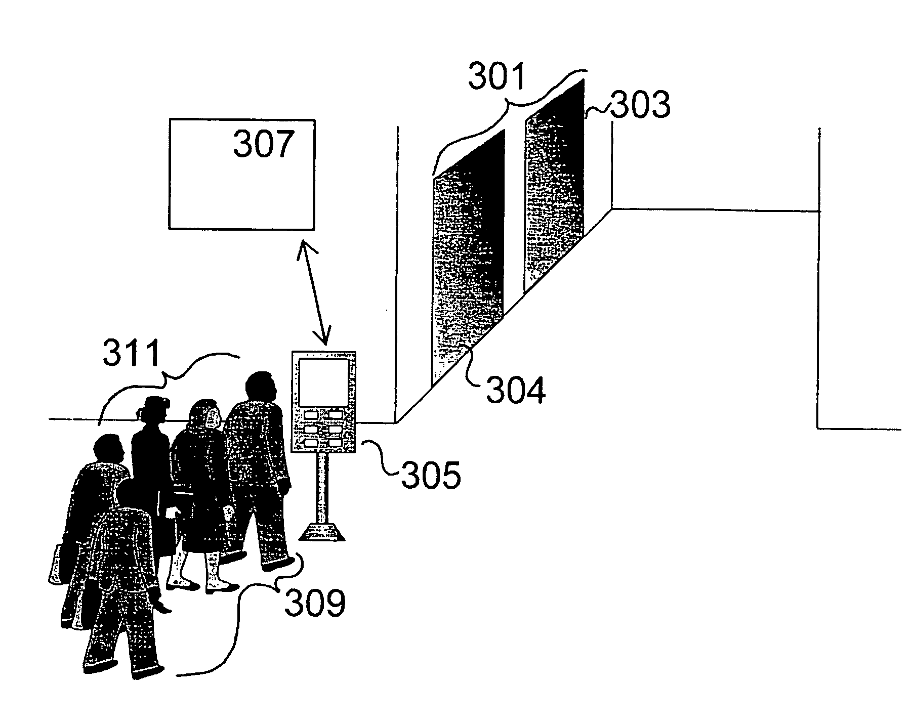
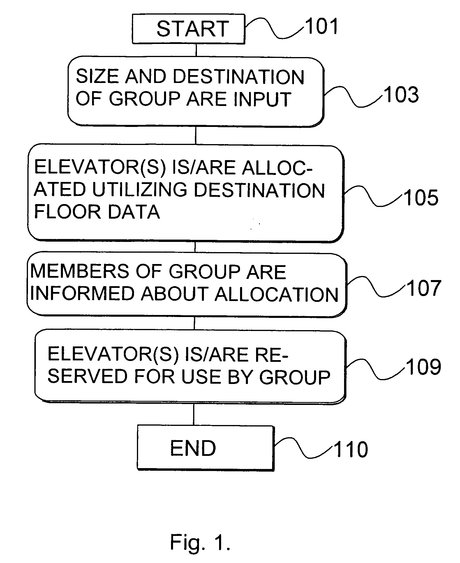
[0019]FIG. 1 presents a flow diagram of the operation of the method of the invention. The method for allocating an elevator is implemented in a destination floor elevator system which comprises an elevator group consisting of several elevators, a passenger data terminal for reserving elevators for use by passengers and an elevator group control system for controlling the elevators, said control system responding to signals from said passenger data terminal. A feature typical of the destination floor elevator system is that a passenger data terminal is provided on the landing level of the building, i.e. on the floor where people arriving in the building enter to wait for elevator transport to their respective destination floors. Via the passenger data terminal, the passenger informs the system about his / her wish to travel to a given destination floor. Destination floor refers to that floor in the building that the passenger wants to reach.

[0020] Execution of the method of the invent...


PUM


Abstract

A method for allocating an elevator in a destination floor elevator system comprising an elevator group consisting of several elevators, a passenger data terminal for reserving elevators for use by passengers, an elevator group control system for controlling the elevators in response to signals from the passenger data terminal. The method of the invention comprises the following steps: the size and destination floor of the group of passengers are input into the control system of the elevator group, one or more elevators are allocated to the group of passengers by utilizing the size and destination floor of the group, and the members of the group of passengers are informed about the allocation.

Description

FIELD OF THE INVENTION [0001] The present invention relates to elevator systems. In particular, the present invention relates to a method for allocating an elevator in a destination floor elevator system which comprises: an elevator group comprising several elevators, a passenger data terminal for reserving elevators for use by passengers, and an elevator group control system for controlling the elevators that responds to signals from the said passenger data terminal. BACKGROUND OF THE INVENTION [0002] In destination floor elevator systems, each passenger wanting to enter an elevator gives at the building's landing level the destination floor to which he / she wants to travel. The destination floor is given by using a passenger data terminal specially reserved for this purpose, such a terminal being an extended version of a landing call button. The actual landing call button has been extended by adding a more versatile user interface allowing the user, i.e. the passenger, to indicate ...

Claims


Application Information

Patent Timeline
Patent Type & Authority Applications(United States)
IPC IPC(8): B66B1/18B66B1/46
CPCB66B1/462B66B1/468B66B2201/4661B66B2201/463B66B2201/4615B66B1/46
Inventor YLINEN, JARIKAKKO, MARKKU
Owner KONE CORP
Why Eureka
Try Eureka