Clamp with a mounting element content

a technology of mounting element and clamping band, which is applied in the direction of scaffold accessories, washstands, lightening support devices, etc., can solve the problems of reducing, for example, the selection of materials

Active Publication Date: 2007-01-25
NORMA GERMANY GMBH
View PDF12 Cites 12 Cited by
  • Summary
  • Abstract
  • Description
  • Claims
  • Application Information

AI Technical Summary

Benefits of technology

[0007] Therefore, it is the primary object of the present invention to provide a clamp of the above-described type in which there are fewer limitations with respect to the connection of clamp band and a mounting element.

Problems solved by technology

This reduces, for example, the selection of possible materials.

Method used


Image

  • Clamp with a mounting element content
  • Clamp with a mounting element content

Examples


Embodiment Construction

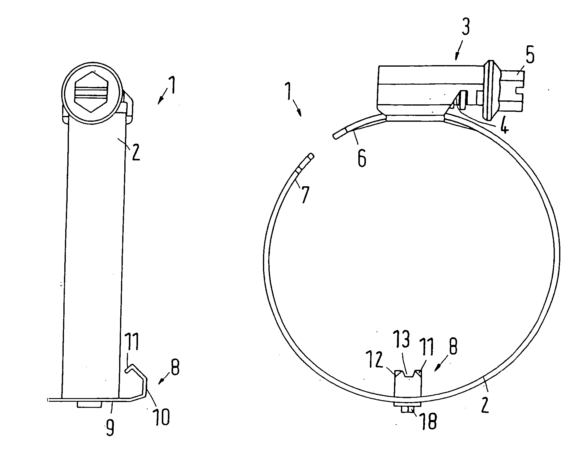
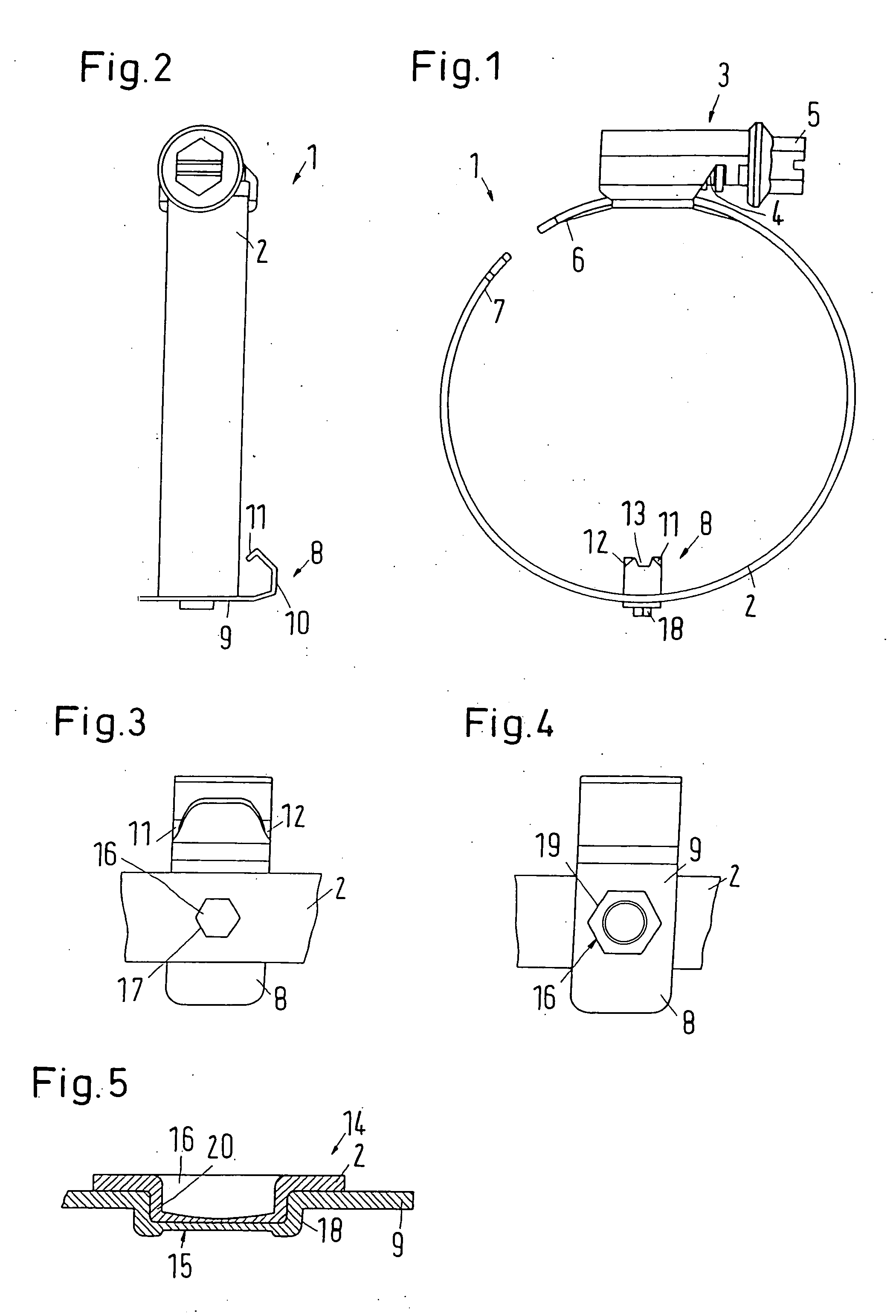
[0024] As illustrated in the drawing, a worm gear clamp 1 includes a clamp band 2. A housing 3 is arranged in the area of an end of the clamp band 2. A tightening screw 4 with a head 5 is rotatably mounted in the housing 3.

[0025] The clamp band 2 has a first end section 6 which is arranged adjacent the housing 3, and a second end section 7 at the other end. The end section 7 has, in a known manner and therefore not illustrated, threaded elements in the form of approximately axial grooves formed in the clamp band 2. These grooves can be placed in engagement with the thread of the tightening screw 4. By turning the tightening screw 4, the worm gear clamp 1 is tightened.

[0026] A mounting element in the form of a prepositioning clip 8 is attached to the clamp band 2. The prepositioning clip 8 has a fastening section 9 which extends approximately perpendicularly of the circumferential direction of the clamp band 2. The prepositioning clip 8 is arranged on the radial outer side of the c...


PUM


Abstract

A clamp with a clamp band and a mounting element which is connected to the clamp band. In a clamp band of the above-described type, this object is met by connecting the mounting element to the clamp band with a clinch connection. The clinch connection may have a polygonal cross-section. The clamp band and the mounting element may be formed of different materials at least in areas where they contact each other.

Description

BACKGROUND OF THE INVENTION [0001] 1. Field of the Invention [0002] The present invention relates to a clamp with a clamp band and a mounting element which is connected to the clamp band. [0003] 2. Description of the Related Art [0004] A clamp of the above-described type is used particularly for fastening a hose to a pipe piece or pipe end. For facilitating the assembly, it is known in the art to preposition the clamp relative to the hose. For this purpose, a mounting element can be used which is fixedly connected to the clamp. This mounting element, which maybe constructed, for example, as a clip, engages at the end face of the hose and holds the clamp in position at this location. For mounting the hose, it is then only necessary to simply push the hose over the pipe piece. The clamp can then be tensioned. [0005] It is no longer necessary to mount the clamp on the hose at the location of use. [0006] For fastening the mounting element to the clamp band, thermal methods are used pred...

Claims


Application Information

Patent Timeline
Patent Type & Authority Applications(United States)
IPC IPC(8): F21V21/00F16L33/04F16L33/06
CPCF16L33/08
Inventor LANGE, FRANKHENRICH, DETLEFKRAUSS, MATHIAS
Owner NORMA GERMANY GMBH
Why Eureka
Try Eureka