Ultrasonic Testing Method and Ultrasonic Testing Device Using This

a testing method and ultrasonic technology, applied in the field of ultrasonic, can solve the problems of affecting the inspection effect, affecting the quality of the instrument, and the degree of uniformity of the piece may not be maintained uniformly, so as to achieve the effect of increasing the degree of freedom

Inactive Publication Date: 2008-12-11
JAPAN AEROSPACE EXPLORATION AGENCY +1
View PDF4 Cites 14 Cited by
  • Summary
  • Abstract
  • Description
  • Claims
  • Application Information

AI Technical Summary

Benefits of technology

[0006]It is hence a first object of the present invention, in view of the foregoing aspects, to provide an ultrasonic testing method for, while increasing the degree of freedom for allocating a transmitter and a receiver, ensuring the action of inspection at higher degree of freedom with less limitation of the target area of a test piece to be inspected and to an ultrasonic testing device using this ultrasonic testing method.
[0007]It is a second object of the present invention to provide an ultrasonic testing method for allocating a set of receivers thus to improve the efficiency of the action of inspection and to an ultrasonic testing device using this ultrasonic testing method.
[0016]The ultrasonic testing method and the ultrasonic testing device using the method according to the present invention allows each probe to be held by its corresponding probe holding mechanism and the transmitter to be suspended by the support legs of the probe holding mechanism to bridge, with no direct contact, over the propagation path of the plate wave, whereby the plate wave can hardly be interrupted while the allocation of the transmitter and the receiver is improved in the degree of freedom with the target area to be inspected of the test piece less limited thus ensuring a higher effectiveness of the testing action.
[0017]Also, since an extra probe which may be a transmitter or a receiver is disposed between the transmitter and the receiver, either the transmission of plural kinds of the ultrasonic wave or the reception of the ultrasonic wave can be implemented at two or more locations, thus increasing the efficiency of the testing action.

Problems solved by technology

However, if the surface of the test piece is undulated or waved, the incident angle between the transmitter or receiver and the surface of the test piece may hardly be maintained at a uniform degree during the scanning action with no direct contact of the sensor head, thus interrupting the inspecting action with the plate wave.
However, the another method also fails to propagate the plate wave up to the receiver after the point on the propagation path of the plate wave where the transmitter or receiver is placed directly on the test piece, hence permitting no use of two or more of the receivers.
As a result, the degree of freedom of the testing action will be limited due to a limited target area of the test piece.
Also, with no use of two or more transmitters or receivers, the testing action may hardly be improved in the efficiency.

Method used


Image

  • Ultrasonic Testing Method and Ultrasonic Testing Device Using This
  • Ultrasonic Testing Method and Ultrasonic Testing Device Using This
  • Ultrasonic Testing Method and Ultrasonic Testing Device Using This

Examples


first embodiment

[0031]the present invention will be described referring to the accompanying drawings FIGS. 1 to 7.

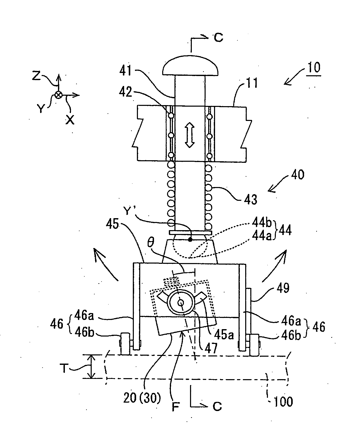
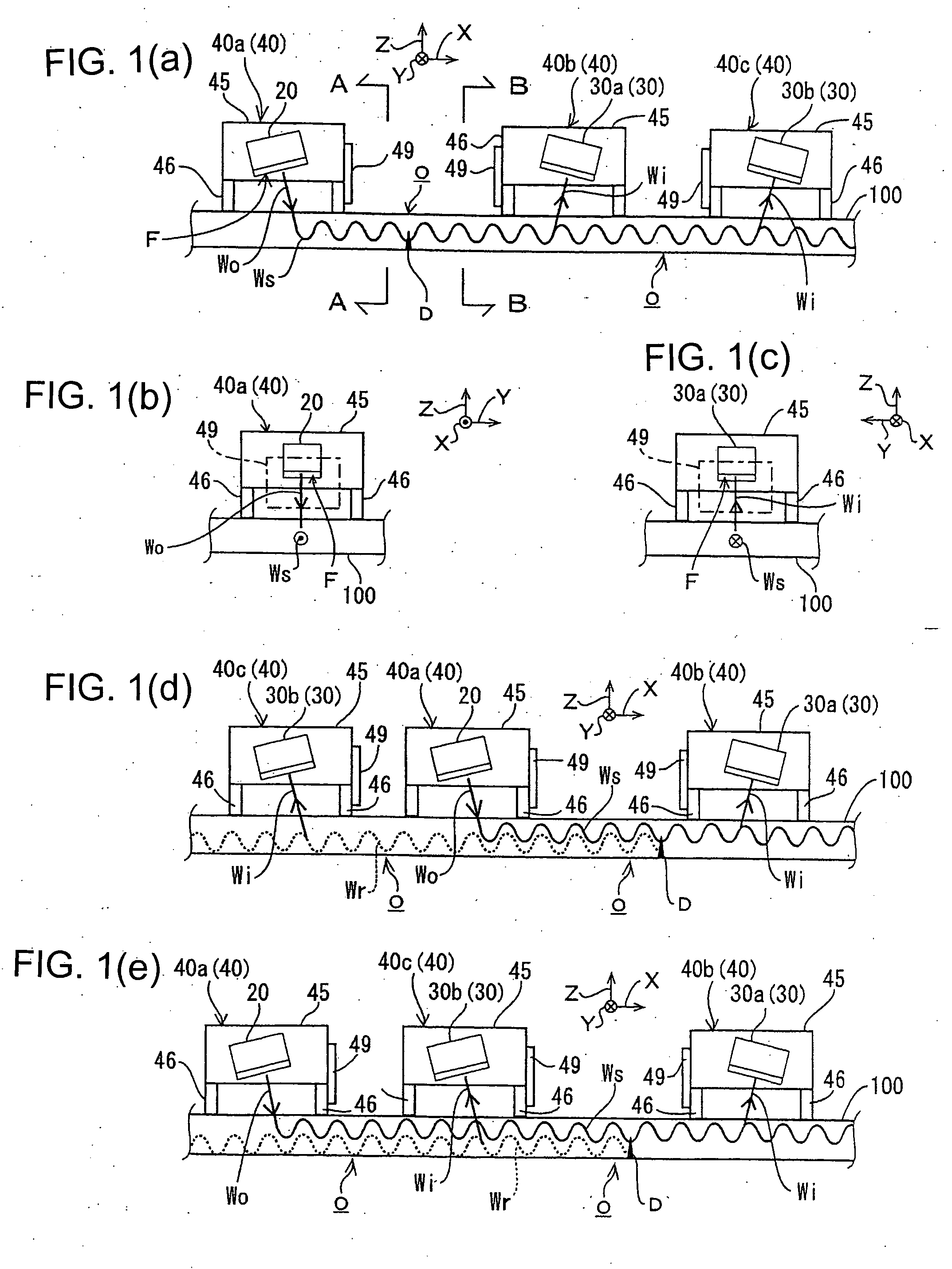
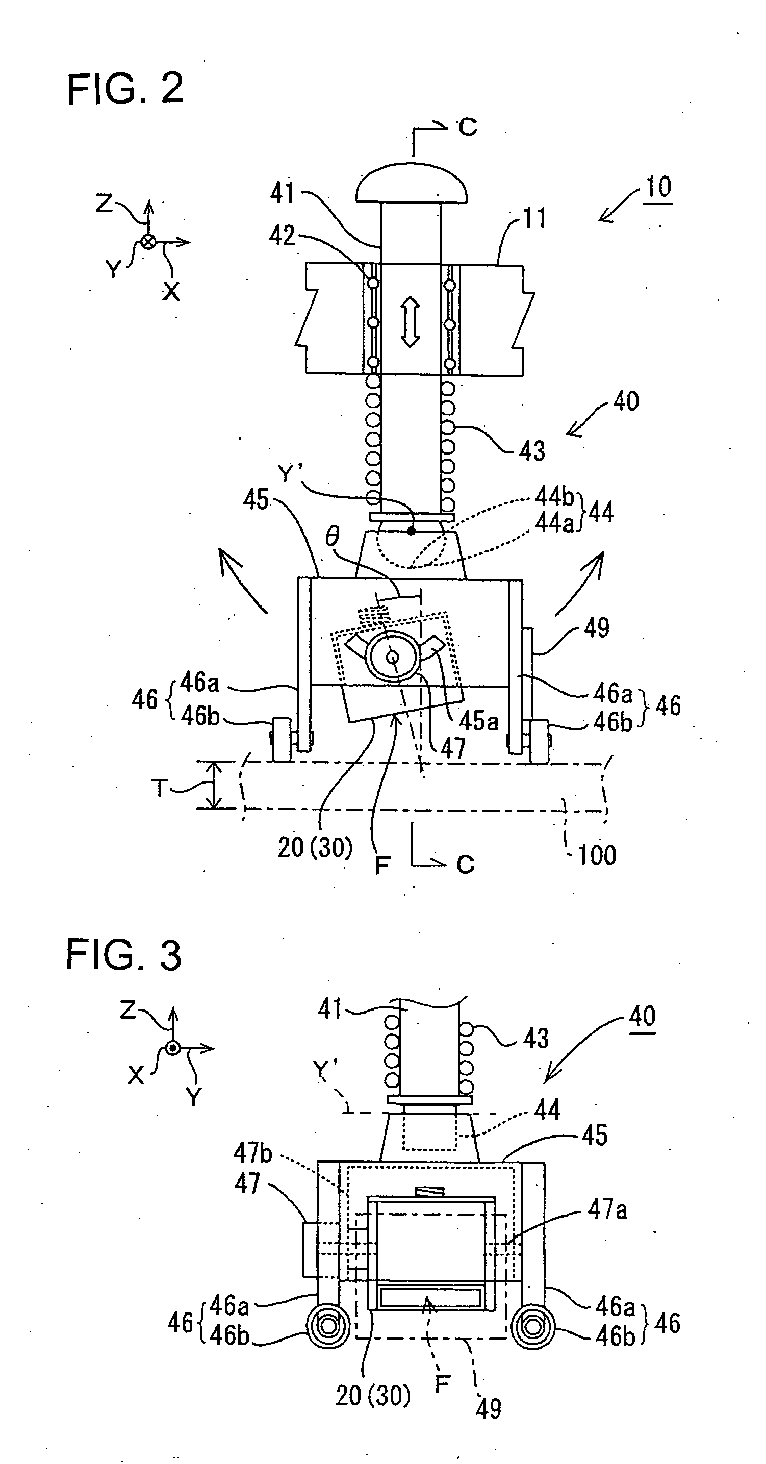
[0032]As shown in FIG. 5 and FIGS. 1A to 1C, an ultrasonic testing device 1 is designed for transmitting an ultrasonic wave from the transmitter 20 in a scan head 10 with the use of a plate wave transducer 3 which is controlled by a personal computer 2 (referred to simply a PC hereinafter). While the ultrasonic wave is propagated between the support legs 46 of a probe holding mechanism 40a which contains a transmitter 20 and the support legs 46 of another probe holding mechanism 40b which contains a receiver 30, it generates a plate wave Ws in a test piece 100. This allows a leak wave Wi to be received and transferred via a pre-amplifier 4, a filters 5, and an A / D converter 6 to the PC 2 where it is subjected to arithmetic operations. The PC 2 also turns a scanner 8 on via a driver 7 for starting the scanning action of the scan head 10 to detect any flaw in the test piece 100. A sensor ...

second embodiment

[0046]FIG. 8 illustrates the present invention in which the transmitter 20 and the receiver 30 are implemented by focusing type probes S2 of which the oscillator is curved. This allows the incident angle θ to be set to a desired degree ranging widely from θ1 to θ2. Accordingly, the testing action can respond to small undulations of the surface of the test piece 100 which may interrupt the action of the probe holding mechanisms 40 and overcome any fitting fault between the support legs 46 and the test piece 100.

[0047]FIG. 9 illustrates a third embodiment of the present invention in which the wheels 46b of the support legs 46 are arranged at a right angle, ninety degrees, to those of the first embodiment. More specifically, the probe holding mechanisms 40 are classified into probe holding mechanisms 40L equipped with the wheels 46b and the transmitters 30 and probe holding mechanisms 40M equipped with the wheels 46b and the receivers 40. Accordingly, since its scanning action along th...

fourth embodiment

[0048]FIG. 10 illustrates the present invention (which is not disclosed in claims but explained as a reference) in which a pair of a probe holding mechanism 40c carrying the second receiver 30b and a probe holding mechanism 40a carrying the transmitter 20 are aligned along the Y direction. Also, a probe holding mechanism 40b carrying the first receiver 30a is provided for receiving a portion of the forward plate wave Ws transmitted across a defect D while the probe holding mechanism 40c receives the reflection Wr of the plate wave.


PUM

PropertyMeasurementUnit
angleaaaaaaaaaa
ultrasonic testingaaaaaaaaaa
angleaaaaaaaaaa

Abstract

A ultrasonic testing method capable of carrying out a test of high degree of freedom where a degree of freedom of arranging a transmission element and a reception element is high and the scope of an object of testing is not likely to be limited, and a ultrasonic testing device using this. An ultrasonic wave is sent from a transmission element (20) to a test element (100) to produce a plate wave in the test element, and the plate wave propagating through the test element is received by a reception element (30) to thereby test the test element on the propagation route of the plate wave. The other probe that is the other reception element (20) or transmission element (30) is disposed between the transmission element (20) and the reception element (30). A probe holding mechanism (40) that has support legs (46) contacting the surface of the test element and keeps constant an angle of the other probe with respect to the surface of the test element is allowed to support the other probe. And, the other probe is allowed to cross over in non-contact the propagation route of the plate wave extending from the transmission element to the reception element by means of support legs (46).

Description

FIELD OF THE INVENTION[0001]The present invention relates to an ultrasonic testing method for transmitting an ultrasonic wave from a transmitter to generate a plate wave in a test piece and receiving at a receiver the plate wave passed through the test piece to inspect the test piece along the propagation path of the plate wave, and an ultrasonic testing device using the ultrasonic testing method.BACKGROUND OF THE INVENTION[0002]One of such ultrasonic testing devices as described above is known where a sensor head is provided comprising two or more of the transmitters and the receivers disposed at both ends of the center point and particularly held at a uniform angle (the incident angle) to the test piece for scanning the surface of the test piece with no direct contact (See Patent Document 1). It is essential for maintaining the incident angle to a uniform degree to match different modes of the relationship between the incident angle of the ultrasonic wave and the product of ultras...

Claims


Application Information

Patent Timeline
Patent Type & Authority Applications(United States)
IPC IPC(8): G01N29/24
CPCG01N29/225G01N29/2487G01N2291/02854G01N2291/0425G01N2291/0427G01N2291/057G01N2291/102G01N2291/2693
Inventor YABUSHITA, HIDEKINAGAI, TATSUYUKIMATSUBARA, SHIGEYUKINEMOTO, NORIOMIYAMOTO, HIROSHI
Owner JAPAN AEROSPACE EXPLORATION AGENCY
Why Eureka
Try Eureka