Bicycle disc brake pad

a technology of disc brakes and brake pads, which is applied in the direction of actuators, coatings, friction linings, etc., can solve the problems of difficult separation of spray coating layer and physical bonded backplate interfaces, and achieve the effect of reducing the difficulty of spray coating layer and physical bonded backplate bonded interfaces

Inactive Publication Date: 2007-03-29
SHIMANO INC
View PDF11 Cites 15 Cited by
  • Summary
  • Abstract
  • Description
  • Claims
  • Application Information

AI Technical Summary

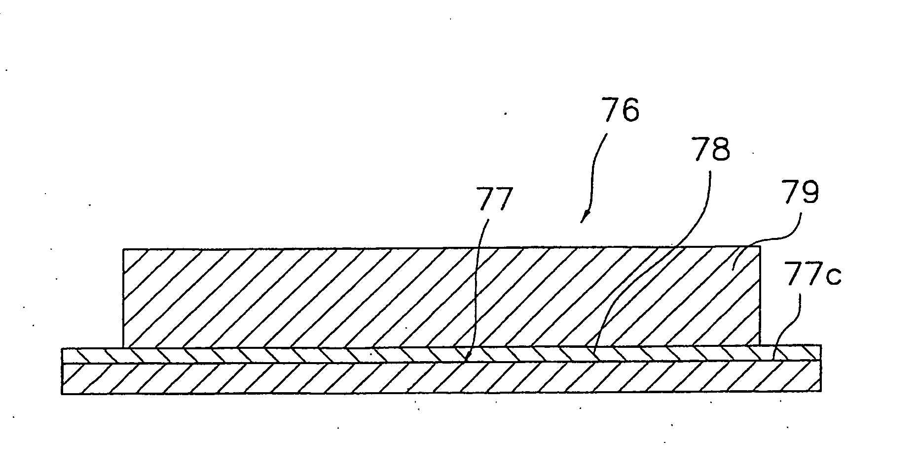
Benefits of technology

[0010] One object of the present invention is to provide a bicycle brake pad that alleviates the restriction placed on the backplate material used for manufacturing bicycle disc brake pads in which the friction member is bonded to the backplate by a diffusion bonding method.
[0011] The foregoing object can basically be attained in accordance with a first aspect of the present invention by providing a bicycle disc brake pad that basically includes a backplate, a spray coating layer and a friction member. The backplate includes a spray coat surface. The spray coating layer contains copper (pure copper or a copper alloy) that is deposited on the spray coat surface of the backplate. The friction member is bonded on the spray coating layer to create a diffusion bond by a diffusion bonding method. In this disc brake pad, a spray coating layer is formed on the backplate by a spray coating method rather than forming a plating layer. A friction member is formed on the spray coating layer by, for example, sintering, and the friction member is bonded to the spray coating layer by a diffusion bonding method. When the spray coating layer is formed by a spray coat method, the backplate is roughened so that a spray coating layer with a rough surface is formed on the surface of the backplate. Furthermore, a rough surface can also be formed by shot blasting and the like so as to produce a surface roughness on the spray coating layer before spray coating. The miniscule concavo-convexities of the spray coat surface are permeated and solidified by the spray coat particles of copper or copper alloy. The so-called anchor effect makes it difficult for the bonded interface of the physically bonded backplate and spray coating layer to separate. Since the spray coating layer is physically bonded to the backplate by the anchor effect, materials of diverse qualities may be used for the backplate insofar as the material possesses the quality of being capable of forming a rough surface for the spray coat surface by performing shot blasting beforehand so as to increase the surface roughness by spray coating. Therefore, there are fewer limitations placed on the qualities of the backplate compared to when a plating layer is chemically bonded with the backplate by diffusion bonding.
[0012] The bicycle disc brake pad according to a second aspect of the present invention provides the pad of the first aspect of the present invention with the backplate being formed of titanium or titanium alloy. In this case, since the backplate is formed of titanium or titanium alloy, the backplate has reduced weight with expected higher strength compared to other light-weight metals such as aluminum and the like.
[0013] The bicycle disc brake pad according to a third aspect of the present invention provides the pad of the first and second aspects of the present inventions with the spray coat surface of the backplate being formed with a rough surface on at least part of the spray coat surface. In this case, the anchor effect relative to spray coating layer is enhanced by the rough surface formed beforehand, thereby increasing the adhesion of the spray coating layer.
[0016] According to the present invention, since the spray coating layer is physically bonded to the backplate by the anchor effect, materials of diverse qualities can be used for the backplate insofar as the material possesses the quality of being capable of forming a rough surface for the spray coat surface by performing shot blasting beforehand so as to increase the surface roughness by spray coating. Therefore, there are fewer limitations placed on the qualities of the backplate compared to when the backplate is chemically bonded to a plating layer by diffusion bonding.

Problems solved by technology

The so-called anchor effect makes it difficult for the bonded interface of the physically bonded backplate and spray coating layer to separate.

Method used


Image

  • Bicycle disc brake pad
  • Bicycle disc brake pad
  • Bicycle disc brake pad

Examples


Embodiment Construction

[0027] Selected embodiments of the present invention will now be explained with reference to the drawings. It will be apparent to those skilled in the art from this disclosure that the following descriptions of the embodiments of the present invention are provided for illustration only and not for the purpose of limiting the invention as defined by the appended claims and their equivalents.

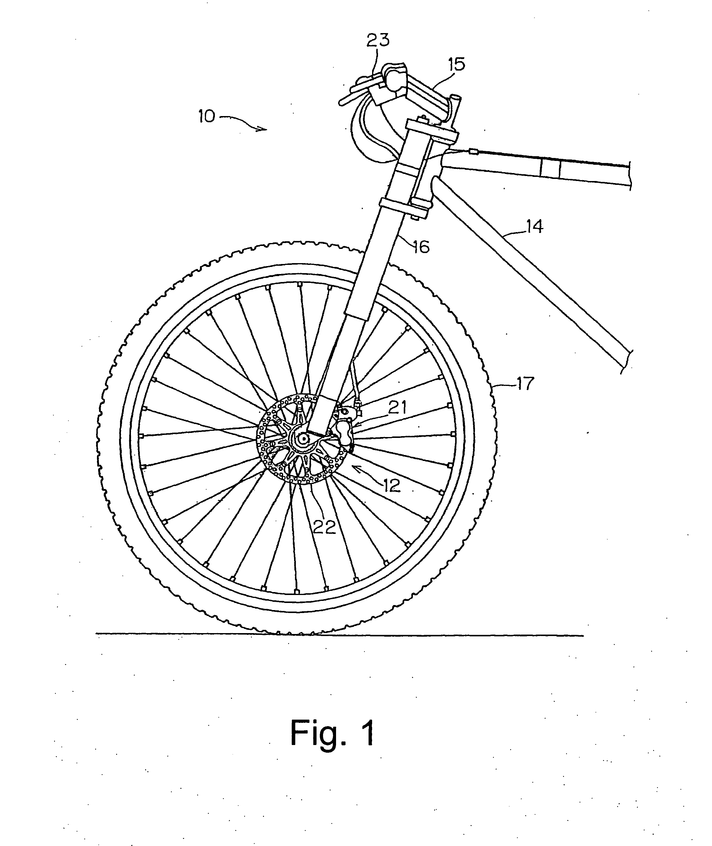
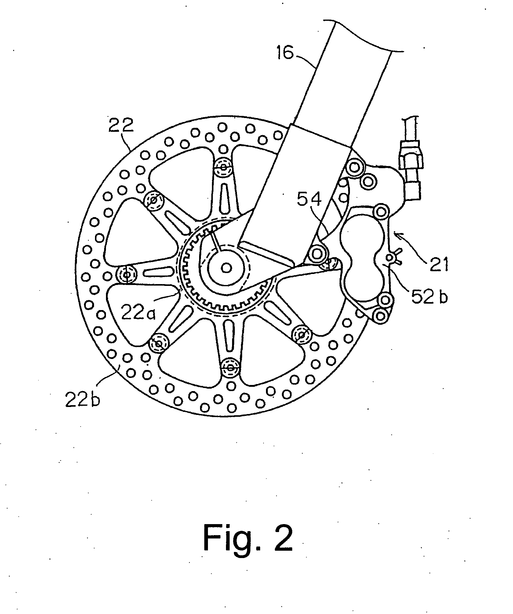
[0028] Referring initially to FIG. 1, a bicycle 10 is illustrated that is equipped with a bicycle disc brake device 12 in accordance with a preferred embodiment of the present invention. The various parts and / or components (technology) of bicycles such as the bicycle 10 are generally well known in the bicycle art. Accordingly, the bicycle 10 and the various structural and operating components of the bicycle 10 will not be described and / or illustrated in detail herein, except as related to the bicycle disc brake device 12 of the present invention.

[0029] The bicycle 10 is conventionally known, exc...


PUM

PropertyMeasurementUnit
thicknessaaaaaaaaaa
sizeaaaaaaaaaa
sizeaaaaaaaaaa

Abstract

A bicycle disc brake pad is used in a disc brake device and is configured to reduce restrictions on backplate material in a disc brake pad for a bicycle in which a friction member is bonded to a backplate by a diffusion bonding method. The bicycle disc brake pad has a backplate, a spray coating layer and a friction member. The surface of the backplate has a spray coat surface. The spray coating layer is a copper or copper alloy layer formed on the spray coat surface. The friction member is bonded to the spray coating layer by a diffusion bonding method. Preferably, the spray coat surface of the backplate is formed with a rough surface on at least part of the spray coat surface.

Description

CROSS-REFERENCE TO RELATED APPLICATIONS [0001] This application claims priority under 35 U.S.C. § 119 to Japanese Patent Application No. 2005-285055, filed Sep. 29, 2005. The entire disclosure of Japanese Patent Application No. 2005-285055 is hereby incorporated herein by reference. BACKGROUND OF THE INVENTION [0002] 1. Field of the Invention [0003] This invention generally relates to a bicycle brake pad. More specifically, the present invention relates to a bicycle disc brake pad in which a friction member is bonded to a backplate. [0004] 2. Background Information [0005] Bicycling is becoming an increasingly more popular form of recreation as well as a means of transportation. Moreover, bicycling has become a very popular competitive sport for both amateurs and professionals. Whether the bicycle is used for recreation, transportation or competition, the bicycle industry is constantly improving the various components of the bicycle. One component that has been extensively redesigned...

Claims


Application Information

Patent Timeline
Patent Type & Authority Applications(United States)
IPC IPC(8): F16D69/00
CPCF16D69/0408F16D2069/045F16D2250/0069F16D2250/0061F16D2250/0046
Inventor HARA, MASAAKIIWAI, TORUFUJITANI, TAKASHIFUKUTA, TSUKASA
Owner SHIMANO INC
Why Eureka
Try Eureka