Infra-red (ir) sensor with controllable sensitivity

a sensor and infra-red technology, applied in the field of infra-red sensors, can solve the problems of limited sensitivity of flir cameras with photon detector sensor arrays, undesired dark current, and limited snr for a single readout,

Inactive Publication Date: 2007-01-25
OPGAL
View PDF4 Cites 39 Cited by
  • Summary
  • Abstract
  • Description
  • Claims
  • Application Information

AI Technical Summary

Problems solved by technology

Dark current is an undesired part of the detector current, which is present even if the detector is not illuminated.
FLIR cameras with photon detector sensor arrays provide IR images with limited sensitivity.
However, if the sensor array is discharged too frequently (due to a very short detector exposure time), the SNR for a single readout is limited by the noise which is present even in the absence of IR radiation.
The image sensitivity is therefore limited by the ratio of the detector signal and the total noise associated with the process.
The read out time for such large detector formats is relatively long.
In order to obtain a required frame rate for the video signal, the detector exposure time must often be limited, even for low f-number systems.
The limited detection time results in insufficient light collection, which decreases the signal to noise ratio.
Thus, high-resolution FLIR cameras with long readout times often have poor sensitivity.

Method used


Image

  • Infra-red (ir) sensor with controllable sensitivity
  • Infra-red (ir) sensor with controllable sensitivity
  • Infra-red (ir) sensor with controllable sensitivity

Examples


example

[0119] The following example presents the results obtained for IR imaging with readout window pixel grouping. IR imaging was performed with readout windows of 640×480 and 216×112. A grouping factor of one was used for both cases. The image was collected by a 3 to 5 micron FLIR camera, with an f-number of 1.5.

[0120]FIGS. 8a and 8b are IR images of a moving object FIG. 8a shows the lower-sensitivity image obtained with a readout window of 640 by 480 detector elements, while FIG. 8b shows the higher-sensitivity image obtained with a readout window of 216 by 112 detector elements. It is seen that FIG. 8b contains a limited portion of the image shown in FIG. 8a, but with greater clarity and detail.

TABLE 1ENTIRE FIELDWINDOWINGSUBJECTOF VIEW MODEMODEPicture size640 by 480 detector216 by 112 detectorelementselementsDetector exposure time1.47 milliseconds1.47 millisecondsDetector readout time10.25 milliseconds0.81 millisecondsMaximum frame rate at60 Frames / Sec420 Frames / SecITR modeMaximum...


PUM


Abstract

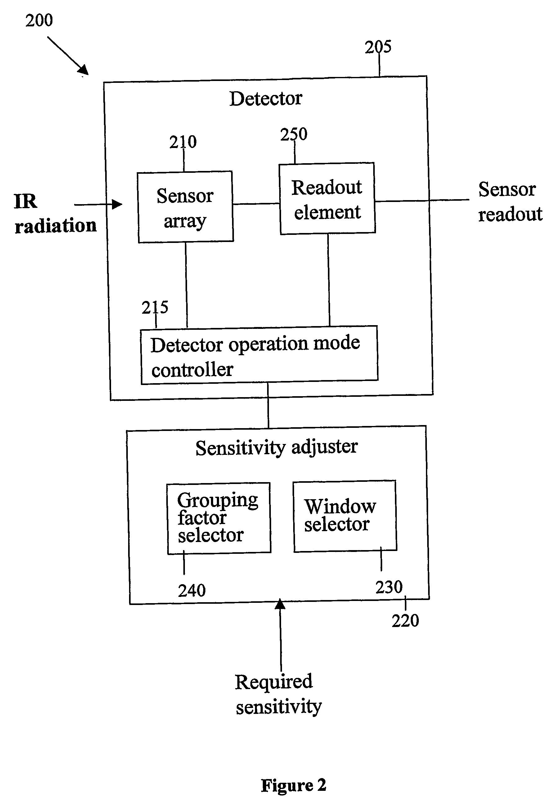
An infrared sensor contains a sensor array and a sensitivity adjuster. The sensor array collects IR energy from an external scene, and the sensitivity adjuster adjusts a pixel grouping for light collection and / or readout, so that the resulting IR image is available at a required sensitivity level.

Description

FIELD AND BACKGROUND OF THE INVENTION [0001] The present embodiments relate to an IR sensor and, more particularly, to and IR sensor with controllable sensitivity. [0002] Infra-red (IR) sensors detect the IR radiation emitted from an object, and are used for day and night vision, non-contact temperature measurement in many industrial, security, and medical applications. These applications include aircraft imaging systems, human temperature sensors, surveillance systems, fire alarms, and night vision equipment [0003] IR sensors generally operate by detecting the differences in the thermal radiance of various objects in a scene. The difference is converted into an electrical signal, which is then processed and analyzed or displayed. Imaging cameras or radiometers, such as forward-looking IR (FLIR) instruments, utilize an array of IR sensors to provide a two-dimensional thermal image. [0004] There are two distinctive sensor technologies: thermal detection and photon detection. Thermal ...

Claims


Application Information

Patent Timeline
Patent Type & Authority Applications(United States)
IPC IPC(8): G01J5/00G01J5/22H04N3/15H04N5/235H04N5/33H04N5/345
CPCG01J5/22G01J2005/0077H04N3/155H04N5/33H04N5/235H04N5/2352H04N3/1562H04N23/72H04N23/70H04N25/443G01J1/02
Inventor GRIMBERG, ERNEST
Owner OPGAL
Why Eureka
Try Eureka