Electric pump

a technology of electric pump and pump body, which is applied in the direction of piston pump, positive displacement liquid engine, liquid fuel engine, etc., can solve the problems of increasing the cost of assembly, and the danger of lowering the magnetic force and an output of the pump

Inactive Publication Date: 2007-01-25
AISIN SEIKI KK
View PDF12 Cites 42 Cited by
  • Summary
  • Abstract
  • Description
  • Claims
  • Application Information

AI Technical Summary

Problems solved by technology

Further, with the configuration of the later described electric pump, if an attempt for reducing a material cost is made, there...

Method used


Image

  • Electric pump
  • Electric pump
  • Electric pump

Examples


Embodiment Construction

[0013] An embodiment of the present invention will be explained hereinbelow with reference to the attached drawings.

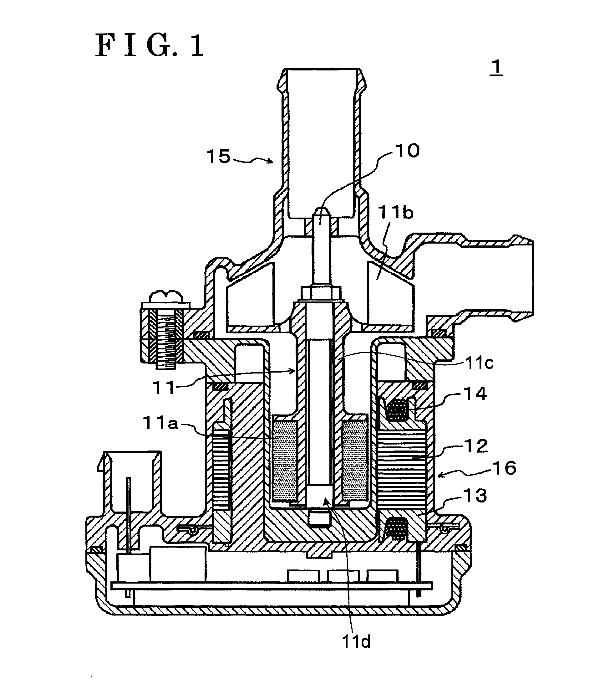
[0014] As illustrated in FIG. 1, an electric pump 1, which is electrically activated and pumps fluid, includes a shaft 10, a rotor 11, a stator 12, a dividing wall 13, winding wires 14, a pump housing 15, and a motor housing 16.

[0015] The shaft 10 is fitted together with a central axis of the rotor 11 by insertion. A first end of the shaft 10 is rotatably supported by the pump housing 15 and a second end of the shaft 10 is rotatably supported by the motor housing 16.

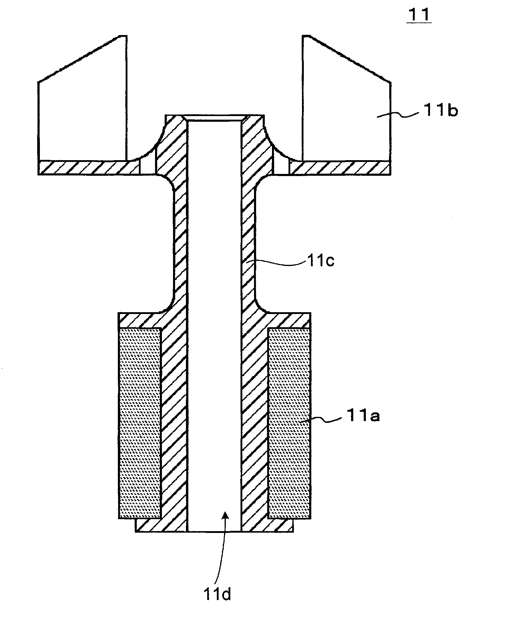
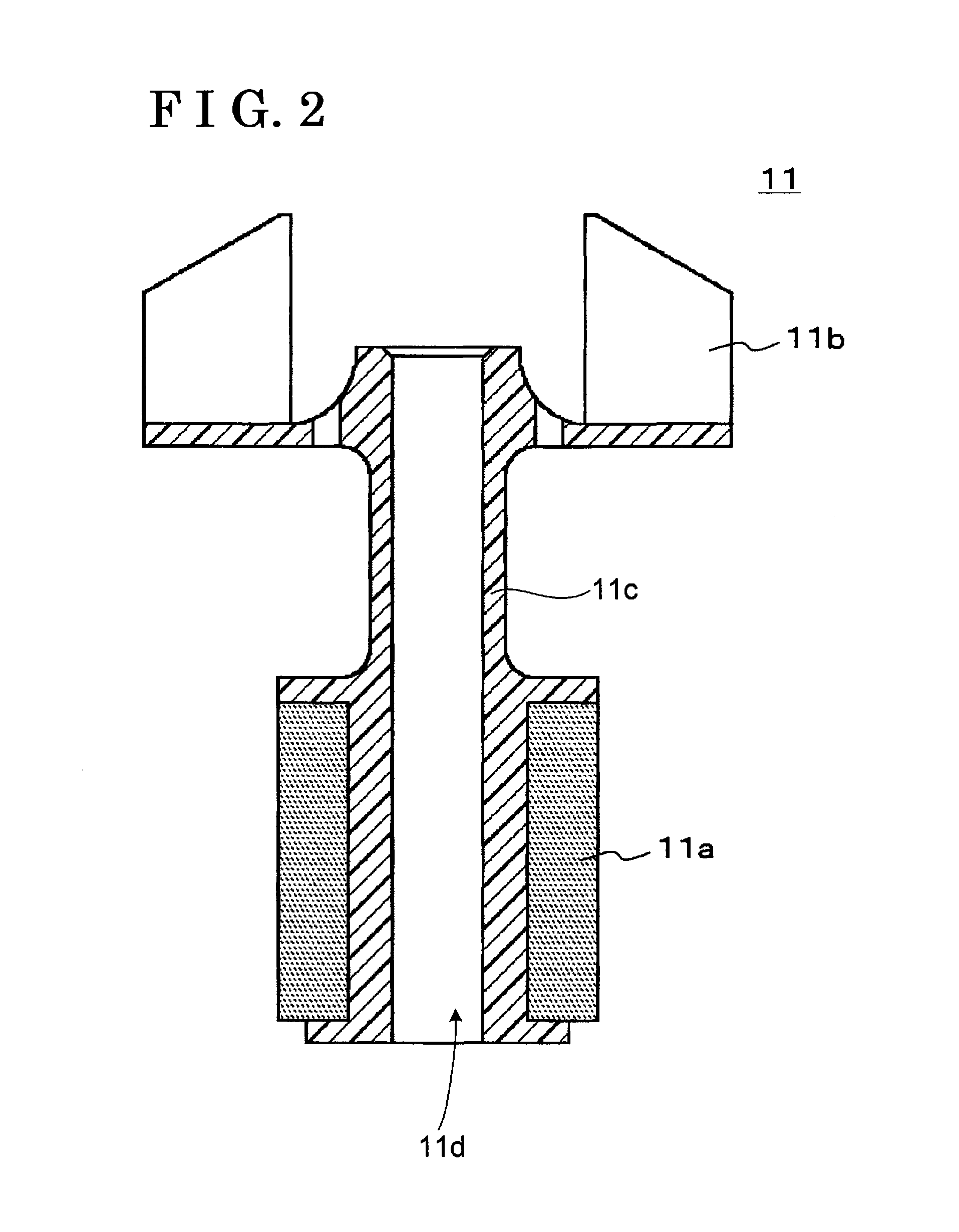
[0016] As illustrated in FIG. 2, the rotor 11 includes a magnet portion 11a, an impeller portion 11b, and a connecting portion 11c. The connecting portion 11c is formed into a substantial tubular shape which includes a hollow portion 11d. The shaft 10 is inserted through the hollow portion 11d of the connecting portion 11c and the rotor 11 is fixed to the shaft 10. The magnet portion 11a is formed at a f...


PUM


Abstract

An electric pump includes a rotor including a magnet portion formed of a ring shaped structure and having a polar anisotropic ring magnet, and an impeller portion pressure-supplying a fluid and formed integrally with the magnet portion, and a stator rotating the rotor.

Description

[0001] This application is based on and claims priority under 35 U.S.C. § 119 to Japanese Patent Application 2005-214859, filed on Jul. 25, 2005, the entire content of which is incorporated herein by reference. FIELD OF THE INVENTION [0002] This invention relates to an electric pump. More particularly, the present invention pertains to an electric pump, which can improve performance and productivity thereof. BACKGROUND [0003] A known electric pump is disclosed in JP2004-308562A. According to the disclosed electric pump, a stator, which is made by winding a coil around a core, is provided in a casing, a shaft is placed in a center of the stator, a rotor is rotatably located at an outer circumference of the stator around the shaft, an impeller is integrally rotatable with the rotor, fluid, which is fed into a pump chamber through an intake hole in accordance with a rotation of the impeller, is exhausted to an outside from an exhaust hole, the shaft is penetrating through the stator an...

Claims


Application Information

Patent Timeline
IPC IPC(8): F04B17/00H02K1/04H02K15/12
CPCF04D29/043F04D29/2222F04D13/064H02K7/14H02K1/2733
Inventor ISHIGURO, MOTOHISAKAMIYA, NAOKIHIGUCHI, TADASHI
Owner AISIN SEIKI KK
Why Eureka
Try Eureka