Universal vehicle head display (HUD) device and method for using the same

a head display and universal technology, applied in static indicating devices, optics, instruments, etc., can solve the problems of enormous financial and faa certification problems of aircraft owners, large design and optical package, and large amount of combiners and optical packages, etc., and achieve the effect of low cost and high functionality

Inactive Publication Date: 2007-01-25
STEWART ROBERT J +2
View PDF21 Cites 124 Cited by
  • Summary
  • Abstract
  • Description
  • Claims
  • Application Information

AI Technical Summary

Benefits of technology

[0018] The engineering design philosophy of the HUD system of the present invention creates a unique configuration that encompasses all aspects of safety, low cost, functionality, human factors and good optical principles, especially for aircraft. Years of aircraft HUD history provide an abundance of resources, hardware configurations and optical layouts that contribute to finding a solution that will meet a variety of difficult requirements. This vast knowledge has led to the present invention embodying a unique and novel design that is highly functional and meets the economic requirements of, among other industries, today's general aviation marketplace.

Problems solved by technology

Field of view requirements, paralleled with the far combiner distance, results in designs that have overly large combiners and optical packages.
It was found that installation and retrofit of these designs, into existing aircraft panels, would cause substantial cutting of the existing structure and repositioning of impacted instruments.
Besides compromising the original aircraft panel and related components, this option would result in tremendous financial and FAA certification issues for the aircraft owner.

Method used


Image

  • Universal vehicle head display (HUD) device and method for using the same
  • Universal vehicle head display (HUD) device and method for using the same
  • Universal vehicle head display (HUD) device and method for using the same

Examples


Embodiment Construction

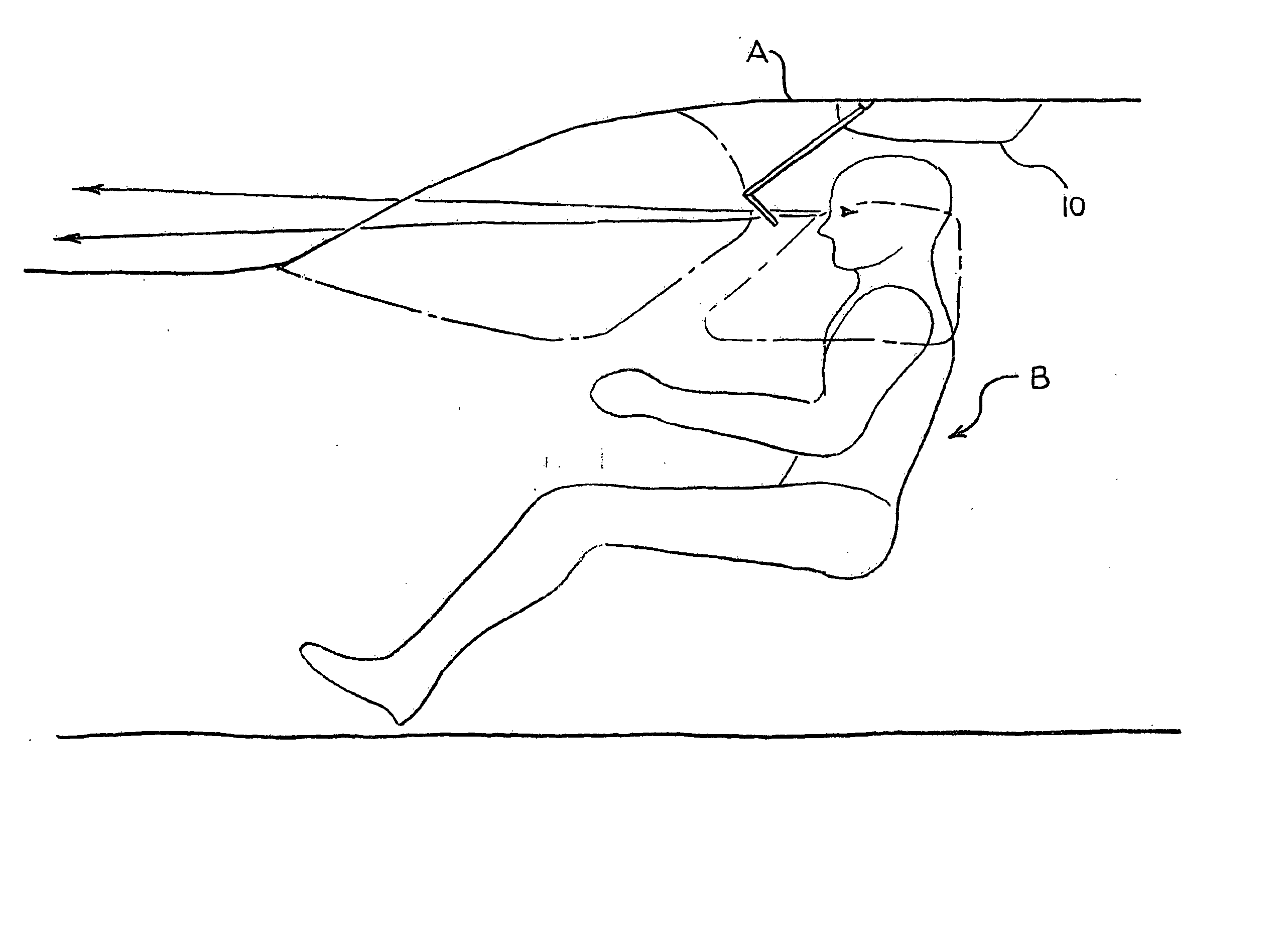
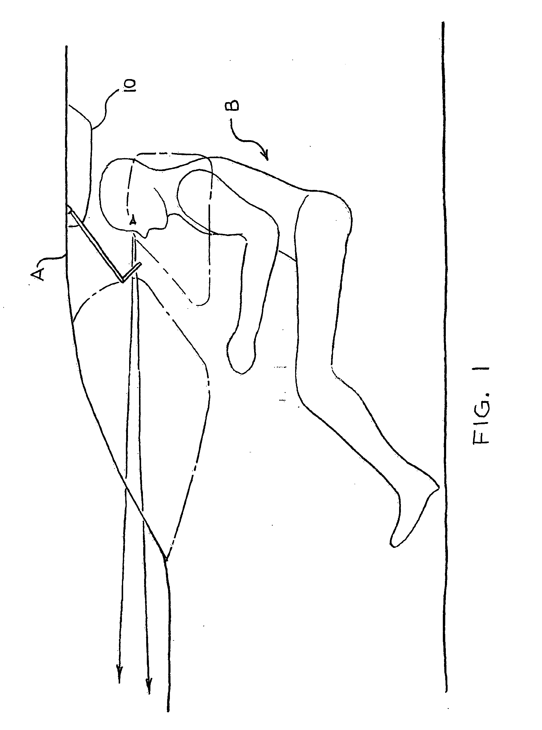
[0058] With reference to the figures, like reference characters will be used to indicate like elements throughout the several embodiments and views thereof. FIG. 1 shows a schematic view of a pilot's cabin or cockpit, wherein the ceiling A of the cabin and the pilot's station B set limits of visibility, i.e., the field of view for the pilot. A HUD 10 is mounted above the pilot's head on the ceiling via fixing means, such as screws or other conventional mounting devices, as will be discussed further hereinbelow. Resin / pin alignment techniques are also applicable for fixing the HUD 10 to the ceiling A.

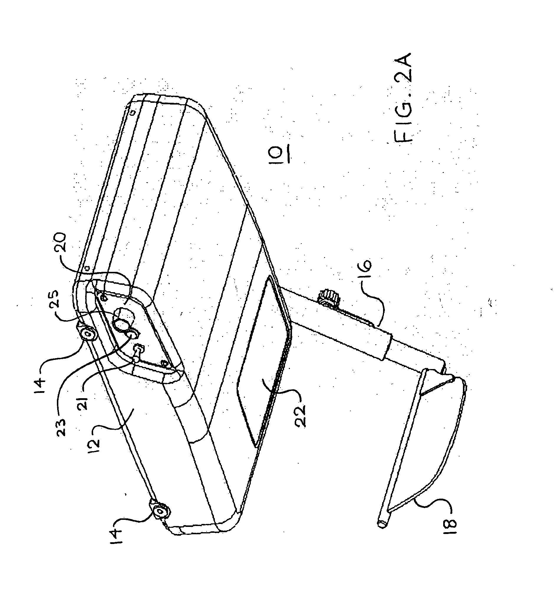
[0059] As shown in FIGS. 2A-2D, the HUD 10 has a housing 12, mounting elements 14, a retractable arm 16, a high resolution display screen / optical combiner 18, control panel 20, and a window 22 visible from outside. Inside the housing 12, (see FIGS. 3C and 3D), there is a controller 34 (in this embodiment, composed of power controller board 34A and digital video board 34B) that provides ...


PUM


Abstract

The invention generally relates to an integrated head up displaying (HUD) device including a housing that houses an active-matrix image projecting system and its accompanying electronics, and an optical combiner (for providing a see-through image thereon) connected to the housing via a retractable arm attached at one end to the main body and holds the HUD optical panel at its other end. In particular, the telescopically retractable arm allows the assembly to extend or retract for a desirable combiner height. Further, the LED backlighting array is placed within a reflective light chamber which is lined with a safe, light-weight, low cost, specular, reflective sheet for high reflectivity. The non-conductive, reflective sheet also covers the LED printed circuit board.

Description

BACKGROUND OF THE INVENTION [0001] 1. Field of the Invention [0002] The invention generally relates to an integrated head up displaying (HUD) device including a housing that houses an active-matrix image projecting system and its accompanying electronics, and an optical combiner (for providing a see-through image thereon) connected to the housing via a retractable arm attached at one end to the main body and holds the HUD optical panel at its other end. In particular, the telescopically retractable arm allows the assembly to extend or retract for a desirable combiner height. Further, the LED backlighting array is placed within a reflective light chamber which is lined with a safe, light-weight, low cost, specular, reflective sheet for high reflectivity. The non-conductive, reflective sheet also covers the LED printed circuit board. [0003] 2. Description of the Related Art [0004] Head-up display (HUD) devices are widely used in vehicles for both business and home purposes. The use of...

Claims


Application Information

Patent Timeline
Patent Type & Authority Applications(United States)
IPC IPC(8): G02B27/14
CPCG02B27/0101G02B2027/0156G02B27/0149
Inventor STEWART, ROBERT J.SMITH, MICHAEL R.STRINGFELLOW, STEVEN A.
Owner STEWART ROBERT J
Why Eureka
Try Eureka