Lighting or indicator device, in particular for motor vehicles
- Summary
- Abstract
- Description
- Claims
- Application Information
AI Technical Summary
Benefits of technology
Problems solved by technology
Method used
Image
Examples
first embodiment
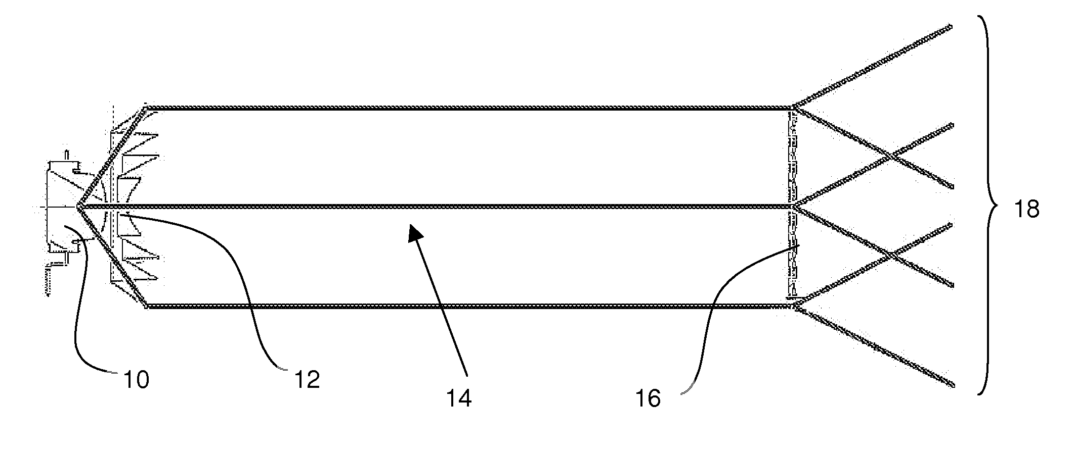
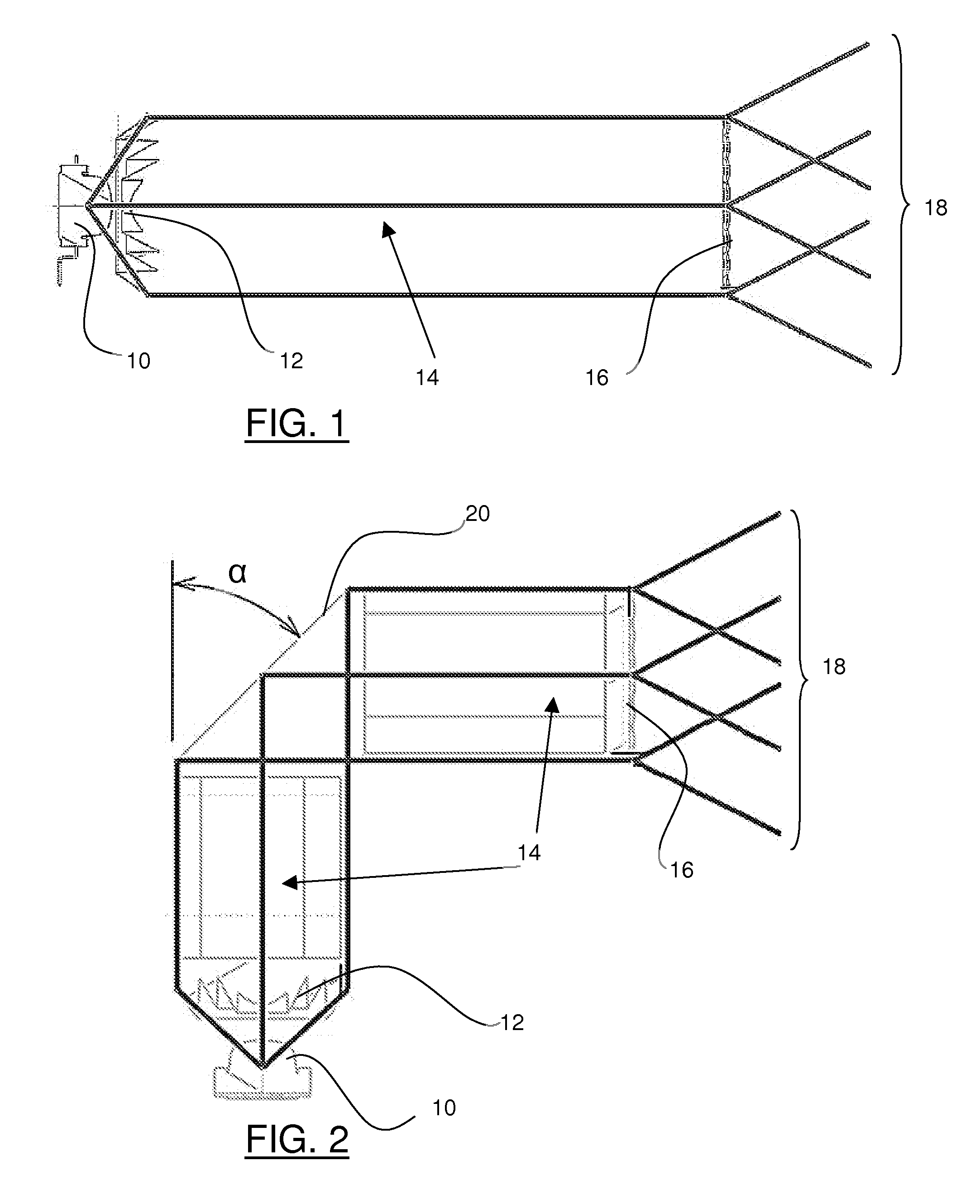
[0060] Various embodiments may be envisaged for the devices in FIG. 1 or 2. In accordance with the first embodiment the input optical system 12 is of one piece with output optical system 16. The volume between input optical system 12 and output optical system 16 is thus formed of the same transparent material as the input and output optical system 16. The lighting or indicator device is thus constructed of a single three-dimensional optical component forming a monobloc module whose transverse cross-section will be advantageously circular, but may also be of a polygonal shape, preferably symmetrical with respect to the optical axis of the device.
[0061] The transparent material used may for example comprise polycarbonate (PC) or polymethylmethacrylate (PMMA), or again glass.
[0062] In this embodiment the input and output optical systems are formed on the extreme surfaces of the volume. The collimating element comprising the input optical system may for example be formed through a conc...
second embodiment
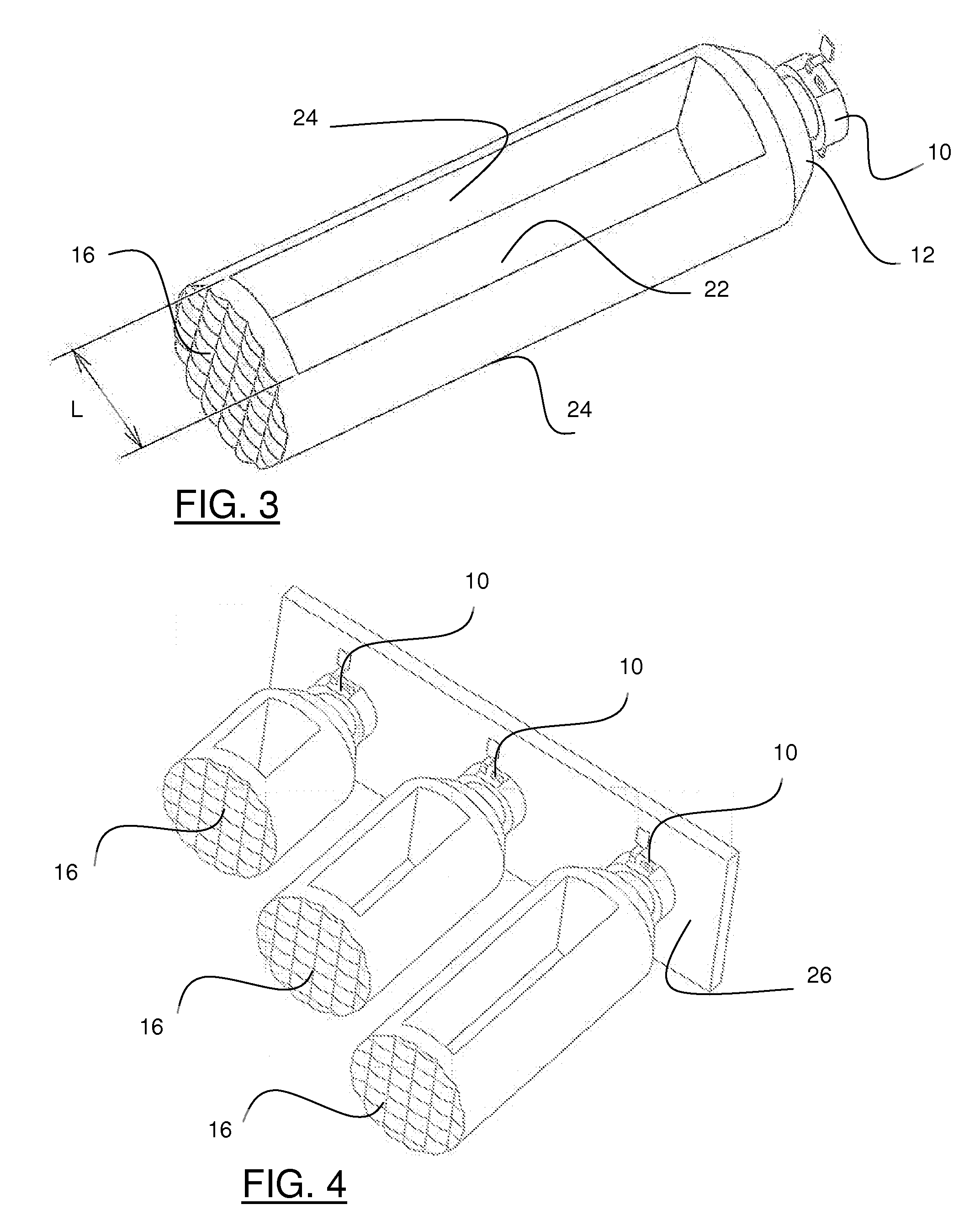
[0065] In accordance with the second embodiment, the input 12 and output 16 optical systems are separated and separate from one another. The volume between the input 12 and output 16 optical systems thus comprises air. In this case the input and output optical systems may be wholly independent of each other, and each supported by a supporting member which ensures that they have a relatively fixed position, in particular aligned with the optical axis of the device. They may also be located at the extremities of the three-dimensional optical piece in the preceding embodiment, this piece having been hollowed out at 22, as shown in FIG. 3, to form a hollow module.
[0066] Void 22 may be formed in any appropriate way, the input and output optical systems being both supported by at least one arm 24, two in the example illustrated, connecting the input and output optical systems. The width L of void 22 is selected to ensure that arms 24 have minimum rigidity. In the example illustrated in FI...
PUM
 Abstract
Description
Claims
Application Information
 - R&D
- Intellectual Property
- Life Sciences
- Materials
- Tech Scout
- Unparalleled Data Quality
- Higher Quality Content
- 60% Fewer Hallucinations
Browse by: Latest US Patents, China's latest patents, Technical Efficacy Thesaurus, Application Domain, Technology Topic, Popular Technical Reports.
© 2025 PatSnap. All rights reserved.Legal|Privacy policy|Modern Slavery Act Transparency Statement|Sitemap|About US| Contact US: help@patsnap.com


