Front discharge concrete mixer truck

Inactive Publication Date: 2007-01-25
SHUMAKER IND
View PDF44 Cites 17 Cited by
  • Summary
  • Abstract
  • Description
  • Claims
  • Application Information

AI Technical Summary

Benefits of technology

[0019] The rationale for designing a new type of concrete mixer truck system is clear. The positive aspects of both machines are to be integrated into one system. The goal is to design a truck that will have better functionality, lower cost and higher salvage value than current front discharge mixer trucks. A rear discharge truck chassis and mixer components will be used in this new design. The drum will be turned to discharge toward the front of the truck in a manner similar to that of the front discharge truck. However the drum will not be lengthened. Chutes will be mounted above and in front of the truck cab and direct concrete to the ground in front of the truck. A conveying system will be used to transport the concrete from the discharge end of the drum to the chutes. In order to support this system, a steel structure will be built on the truck frame rails. By using the rear discharge style components and truck chassis, the proposed design will be less expensive to produce than current front discharge systems. It will also increase salvage value and reliability. The rear discharge style drum will have a larger discharge opening than the front discharge style drums and allow a faster concrete flow rate. The mixer will discharge from the front of the truck at an initial point that is higher than the current front discharge systems, providing a steeper maximum chute inclination angle. The new design will also have a maximum height of 146 inches and therefore be marketable to urban areas. The use of a front discharge style chute system will provide adequate reach and angular range to be comparable with current front discharge mixers. Furthermore, the pour will be controlled from within the truck cab. This will improve pour efficiency and accuracy as the driver will be able to see the pour from the driver's seat. Though the proposed desig

Problems solved by technology

If the concrete producer does not replace the mixer system, the truck has little salvage value.
There are, however, advantages and disadvantages to each truck package.
One of the drawbacks of the rear discharge machine is that the driver must back the truck into certain job sites.
This increases time on the job site and thus contractor costs and producer losses.
The front discharge concrete mixer truck is more expensive than the rear discharge truck.
This chassis package is specifically designed for concrete delivery and does not lend itself to other applications.
Increased customization leads to frequent, difficult and expensive maintenance as well as higher manufacturing costs and low salvage value.
Front discharge truck components, including mixer package components and chassis parts, commonly wear out in about six to ten years.
This is an enormous and frequent expense.
Beyond financial drawbacks, the front discharge mixer has several functional problems.
Front discharge machines have an awkward weight distribution.
The longer frame rails of th

Method used


Image

  • Front discharge concrete mixer truck
  • Front discharge concrete mixer truck
  • Front discharge concrete mixer truck

Examples


Example

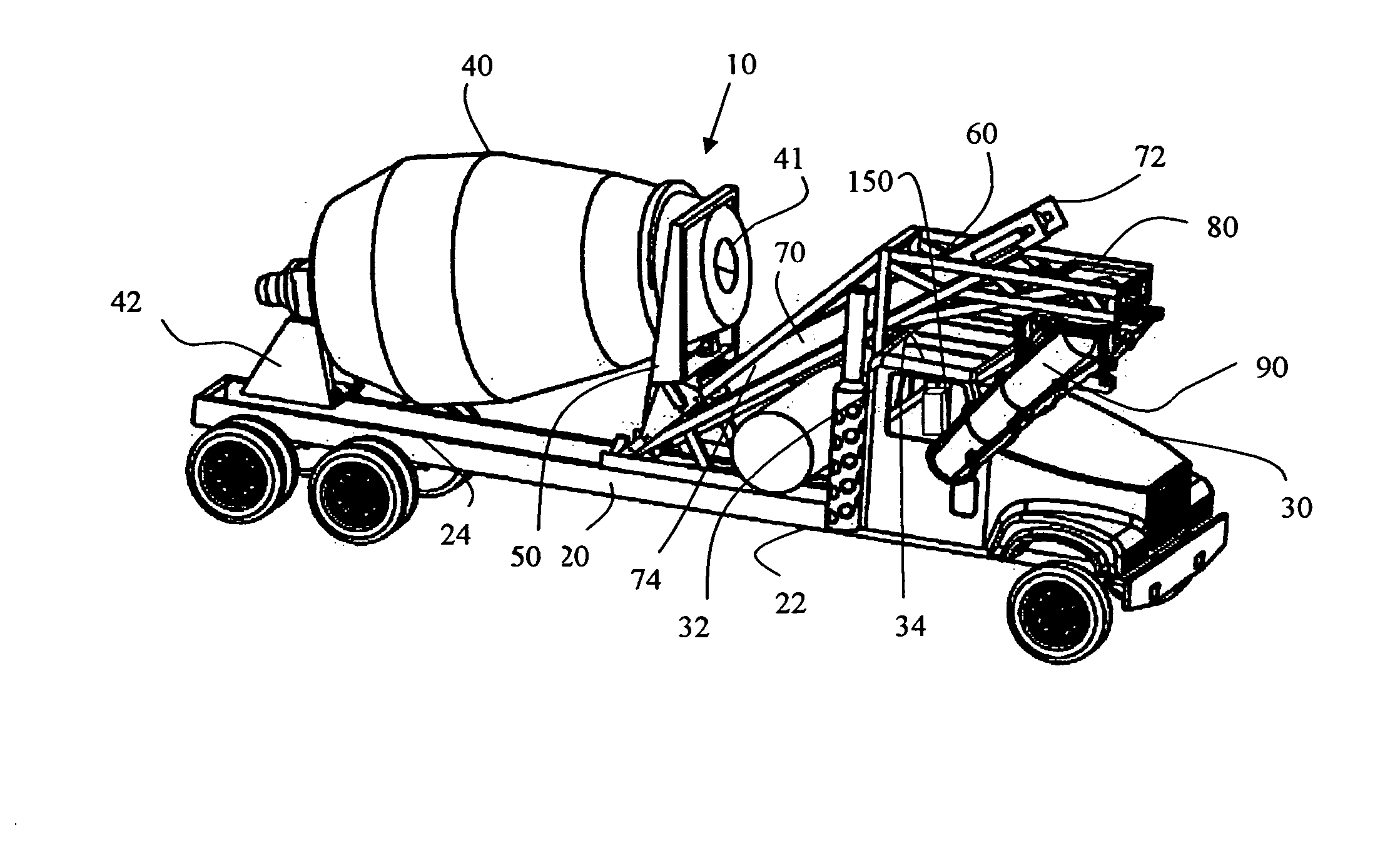
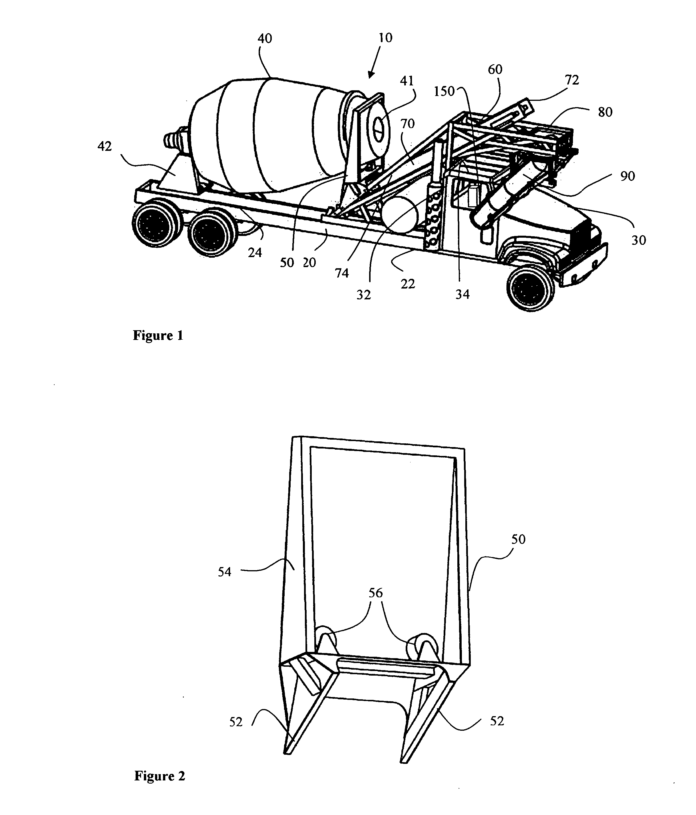
[0070] Referring to FIG. 1, a new type of front discharge concrete mixer truck 10 is shown. Mixer truck 10 includes a chassis 20 which has a forward end 22 and a rear end 24. A cab 30 is mounted on the forward end 22 of the chassis 20 and a mixer drum 40 is attached to the rear end 24 of the chassis 20. The mixer drum 40 is a standard drum of the type typically utilized on rear discharge mixer trucks. The drum, however, is rotated 180° so that the discharge end of the drum 41 faces the back 32 of the cab 30.

[0071] The cab also has a roof 32 which defines an uppermost surface of the cab and a control panel 150 is mounted inside the cab to control the various operations which the mixer truck provides.

[0072] The mixer drum 40 is attached to the chassis 20 but by means of a rear pedestal 42 (which has a configuration identical to a typical front pedestal of a typical rear discharge mixer truck) and is attached at the front end by means of a front pedestal 50.

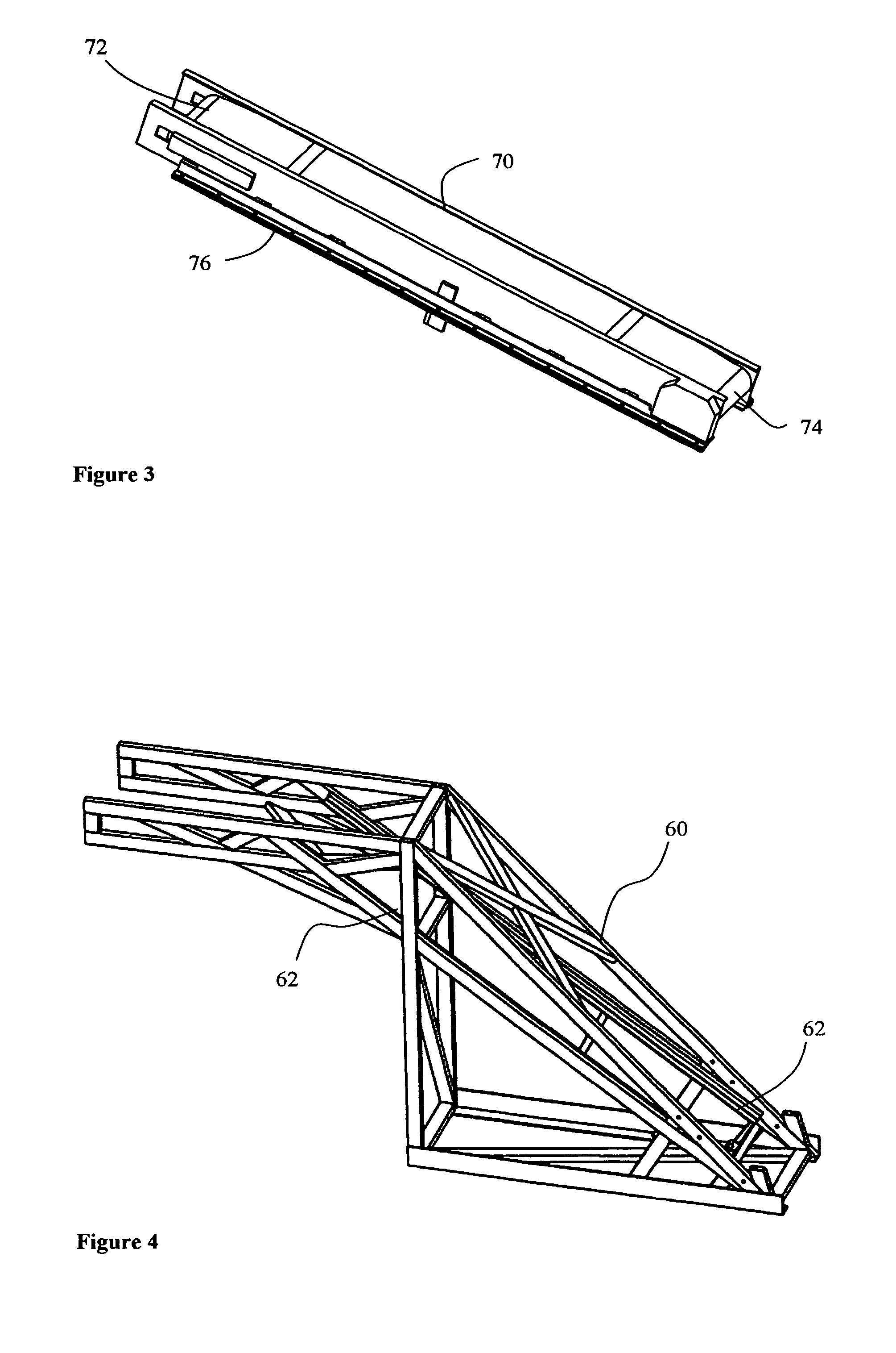
[0073] A support frame 60...


PUM

PropertyMeasurementUnit
Angleaaaaaaaaaa
Shapeaaaaaaaaaa
Heightaaaaaaaaaa

Abstract

A concrete mixer truck includes a truck chassis having a cab mounted at the front of the chassis. A mixing drum adapted to receive, mix and dispense concrete is mounted at a rear end of the chassis. The drum has a discharge end which faces the cab. A collector is located above the cab roof and is spaced apart from the mixing drum. A conveyor device mounted on a support frame is located generally between the cab and the drum and is utilized to transport concrete from the discharge end of said mixing drum up an inclined slope to the collector. A placement chute system directs a gravity flow of concrete from said collector to a desired location. The mixer truck utilizes the chassis, drum and other components of a standard rear discharge mixer truck to create a new type of front discharge mixer which has many of the advantages of existing front discharge mixer trucks at a reduced cost.

Description

BACKGROUND OF THE INVENTION [0001] 1. Field of the Invention [0002] The present invention relates to a front discharge mixer truck. More specifically, it relates to a mixer truck which preferably utilizes a standard class 8 straight truck chassis and a standard rear discharge mixing drum mounted to discharge forwardly with a conveyor device transporting concrete from the drum to a location over the truck cab for front discharge through a placement chute system. [0003] 2. Description of the Prior Art [0004] The concrete production industry uses mixer trucks to transport freshly mixed concrete from a production facility to a job site. There are two types of trucks currently in use by this industry: the rear discharge mixer truck and the front discharge mixer truck. The rear discharge mixer was introduced in the early twentieth century and has undergone few changes since. This truck type composes the majority of the current concrete mixer truck market. A Class 8 straight truck chassis ...

Claims


Application Information

Patent Timeline
IPC IPC(8): B28C5/42
CPCB28C5/4248B28C5/4258B28C5/4255
Inventor SHUMAKER, BRETTTHOMAS, ALLENBEAL, CRAIGKEISER, MATTHEWDECKER, ROBERT VANDERSHOOTER, STEVEN B.
Owner SHUMAKER IND
Why Eureka
Try Eureka