Gear cutting machine, in particular bevel gear cutting machine, having a device for chamfering / deburring the edges of a work piece
- Summary
- Abstract
- Description
- Claims
- Application Information
AI Technical Summary
Benefits of technology
Problems solved by technology
Method used
Image
Examples
Embodiment Construction
[0011] The invention is explained in greater detail by means of preferred embodiments which illustrate the invention by way of example only.
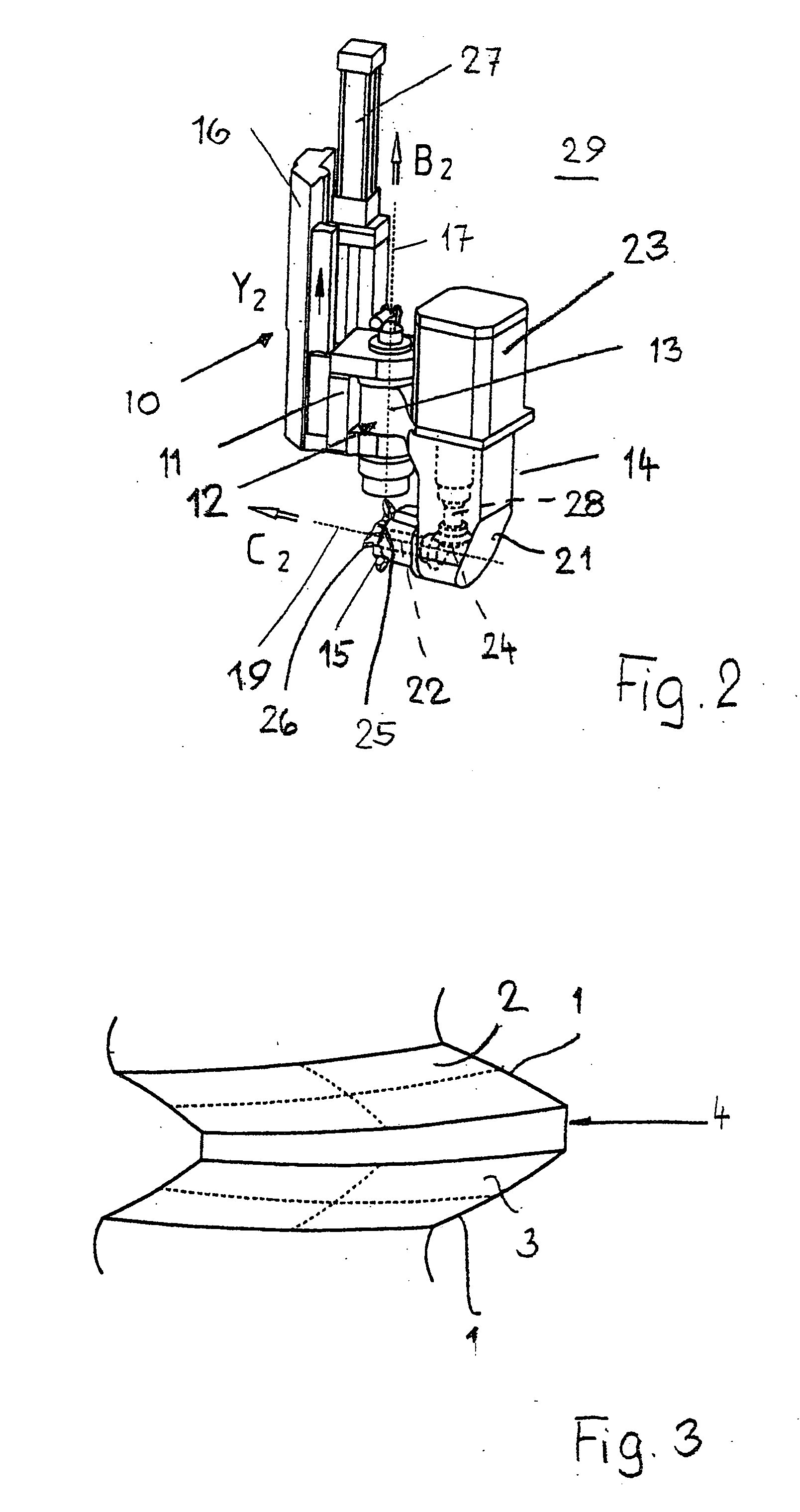
[0012] The device described in the following is used to chamfer and / or deburr the edges 1 between the flanks 2, 3 (FIG. 3) and a back face 4 (obscured in FIG. 3) of a bevel gear. It is also possible to use the device to machine the areas of the edges 1 where the transitions-of the flanks 2, 3 are possibly rounded toward the top (preferably the face cone corner) and / or toward the root (top- and / or root rounding).
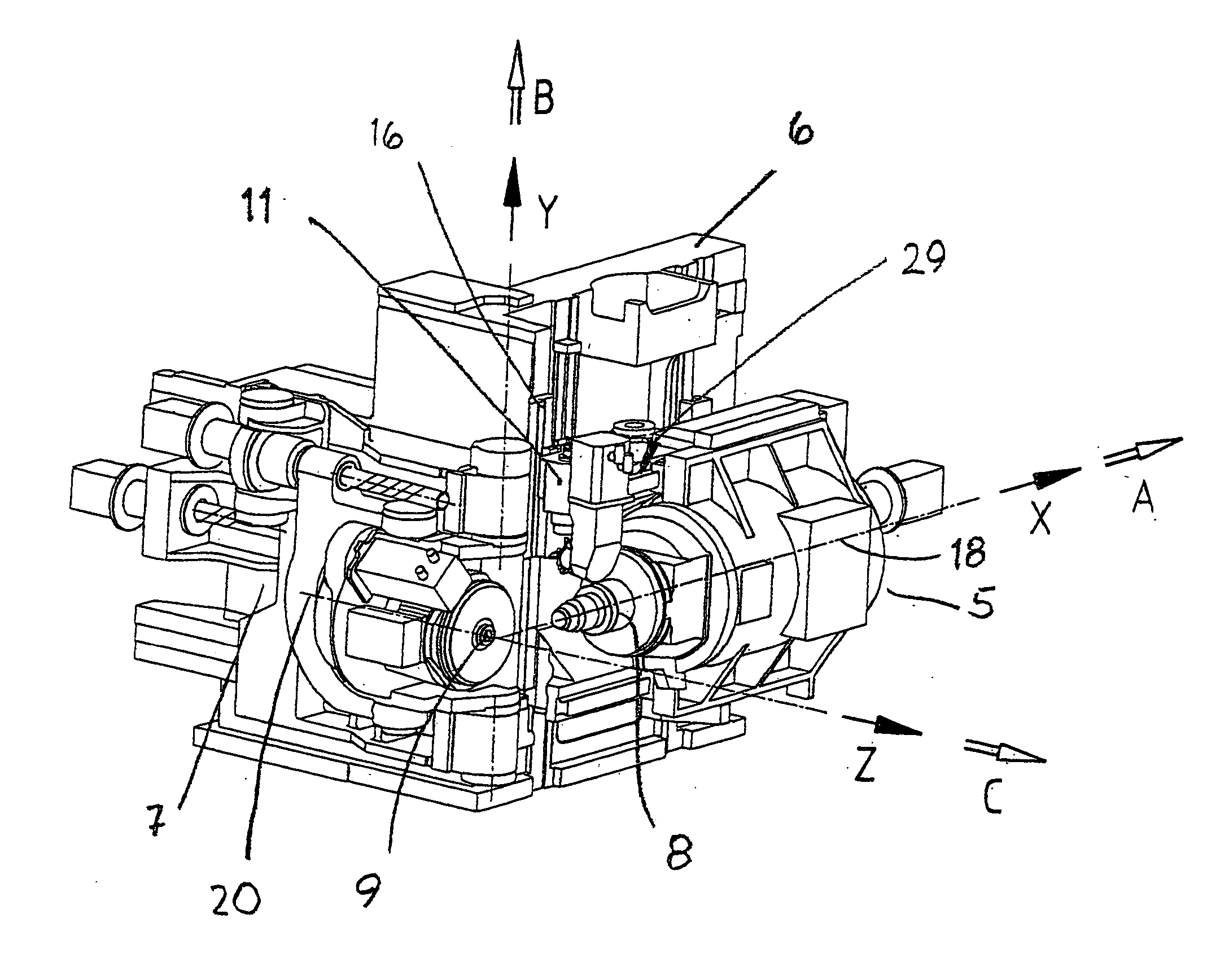
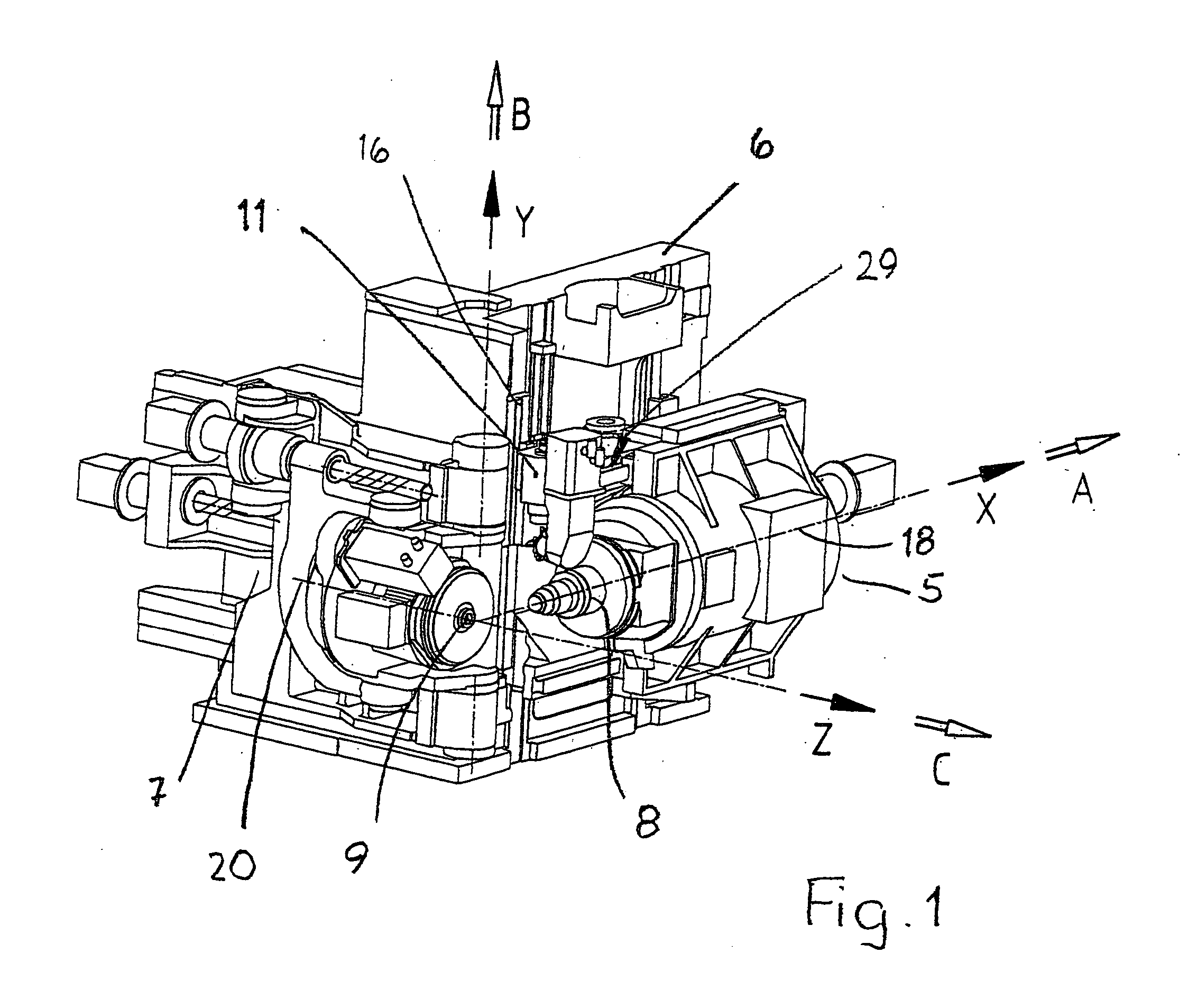
[0013]FIG. 1 shows a machine, such as shown in U.S. Pat. No. 6,712,566 to Stadifeld et al. for example, with the device used for the chamfering and / or deburring provided at the machine, preferably on the machine stationary column or stand 6. The machine is a bevel gear cutting machine and has a work piece carriage 5 that can be moved in direction X (direction of the work piece axis of rotation 18). Furthermore, the work piece carriage 5...
PUM
 Abstract
Description
Claims
Application Information
 - R&D
- Intellectual Property
- Life Sciences
- Materials
- Tech Scout
- Unparalleled Data Quality
- Higher Quality Content
- 60% Fewer Hallucinations
Browse by: Latest US Patents, China's latest patents, Technical Efficacy Thesaurus, Application Domain, Technology Topic, Popular Technical Reports.
© 2025 PatSnap. All rights reserved.Legal|Privacy policy|Modern Slavery Act Transparency Statement|Sitemap|About US| Contact US: help@patsnap.com


