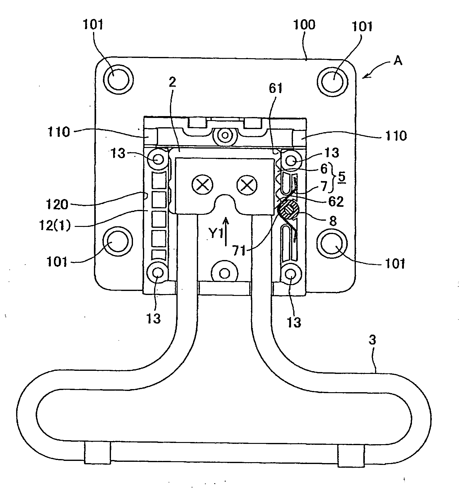
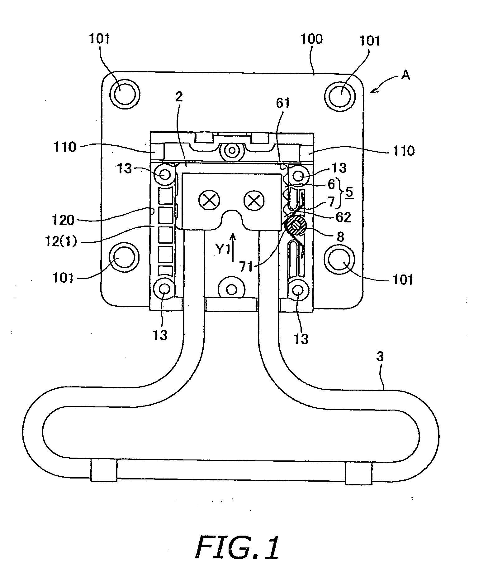
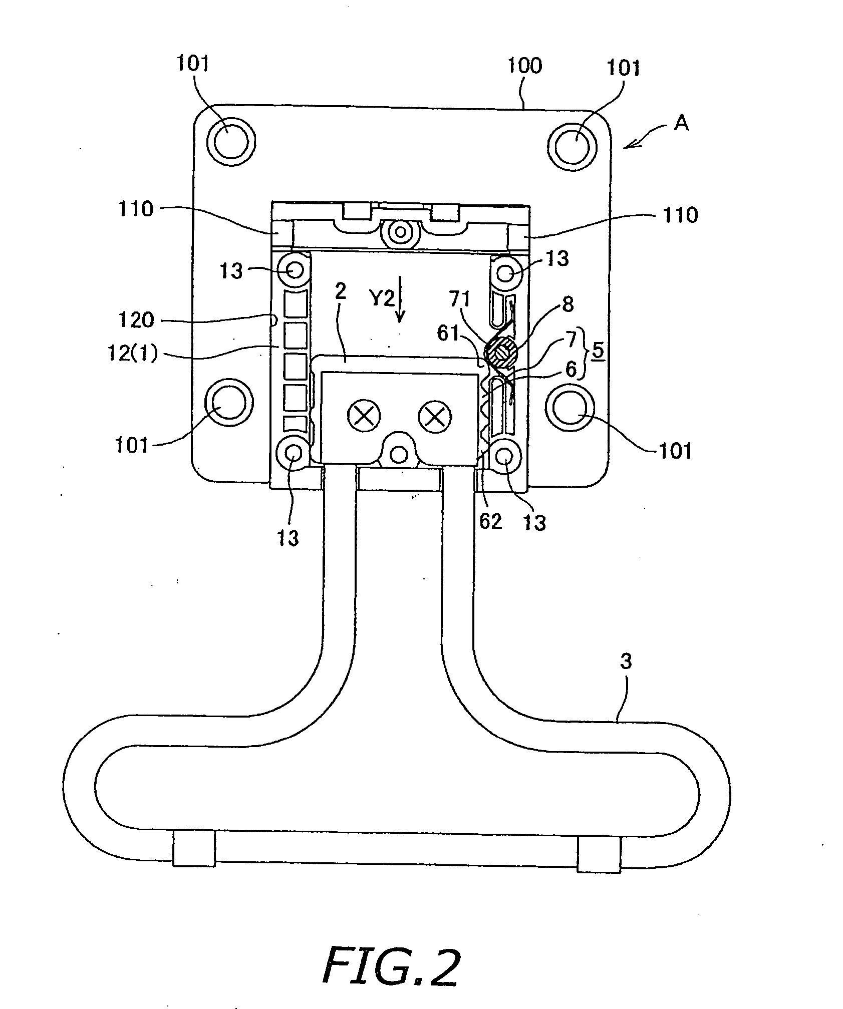
[0019] The display device pertaining to the present invention is a display device comprising a main display component and a stand unit. The main display component have a forward-facing display screen. The stand unit is attached to the main display component and have an extendable leg for supporting the main display component in a tilted orientation, a slider affixed to the upper end of the leg, a case in which the slider is housed so as to be capable of sliding up and down, and slider position restriction means interposed between the slider and the case, for restricting the slider to two positions consisting of an upper position and a lower position within the case, thereby allowing the leg to be extended from the case in two protrusion lengths. The slider position restriction means include a
cam component provided on one side of the slider and the case and having an upper latching component for an upper end and a lower latching component for a lower end, an engagement component provided on the other side and allowing the upper latching component and the lower latching component to be selectively latched, and a spring for constantly elastically biasing the engagement component toward the cam component. The cam component being equipped with a wavy serrated face that links the upper latching component and the lower latching component and increases the moving resistance when there is relative movement of the engagement component between the two latching components.
[0020] With this constitution, when the main display component is being supported in a tilted orientation by the leg, even if too great a load should be applied to the engagement component of the spring latched by the upper latching component of the cam component, so that the upper latching component of the cam component comes off from the engagement component, since a state is created in which the wavy serrated face linked to the upper latching component of the cam component is hooked to the engagement component that is biased by the spring, there is increased moving resistance when the engagement component slides over this serrated face. As a result, it is unlikely that a situation will occur in which the leg is pushed back in by the sliding of the engagement component over this serrated face. Therefore, if the main display component is larger and heavier, or if some kind of external pressing force is exerted on the main display component, the rearward collapse of the main display component caused by the leg being pushed in and its
effective length being shortened can be prevented.
[0021] It is possible with the present invention to employ a constitution in which a
leg length adjusting function of restricting the protrusion length of the leg from the case to one or more stages by latching and positioning the engagement component is imparted to the serrated face. This allows the effective length of the leg to be adjusted to
multiple stages by engaging the engagement component with the serrated face. Accordingly, an
advantage is that the tilt angle of a display that is supported by the leg in a tilted orientation can be adjusted over
multiple stages.
[0022] With the present invention, the spring is preferably a
leaf spring having a peaked portion whose apex forms the engagement component, and a pair of seats that extend from the ends of the peaked portion and are supported so as to be displaced up and down by deformation of the peaked portion accompanying the
lateral extension and retraction of the engagement component. Employing this constitution allows the shape and structure of the spring to be simplified, and allows the cost of producing the spring to be kept low.
[0025] With the present invention, when the elasticity of the spring is set low enough that the leg can be extended or retracted and its effective length thereby lengthened or shortened by hand, and furthermore is set high enough to allow the main display component to be supported in a tilted orientation, the cam component will not slide over the engagement component, causing the leg to be pushed in, even if some kind of external pressing force should be exerted that would cause the upper latching component to come off from the engagement component, which is accomplished merely by providing a wavy serrated face to the cam component and thereby linking the lower latching component and upper latching component. Accordingly, the problem of the leg supporting the main display component in a tilted orientation being unintentionally pushed in so that the main display component falls over backwards is prevented without greatly modifying the structure of the stand unit described through reference to FIGS. 7 and 8, and furthermore without adding any new parts. Therefore, even if the main display component should be unintentionally pushed by hand while the user is viewing the images on the display screen of the main display component, the main display component will not fall over backwards, and a stand unit for supporting a lighter main display component can be used without modification to support a larger and heavier main display component, which allows parts to be shared and boosts the productivity of the display devices.
[0026] Also, there is a provided an elasticity adjustment means for increasing or decreasing the elasticity of the spring, and merely by increasing or decreasing the biasing force of the spring on the engagement component, it is possible to strike a suitable balance between the amount of operating force required for extending or retracting the effective length of the leg, and the biasing force of the spring required to support the main display component so that it will not fall over. As a result, the stand unit is more versatile, and even though the main display component will not fall over backwards, the operation of extending or retracting the leg can be carried out with ease.
