Mounting base for robot

A technology for installing bases and robots, which is applied in the field of robots, can solve the problems of inconvenient robot adjustment and change, poor use of robots, and robot offsets, etc., to achieve the effects of preventing position offsets, facilitating movement and positioning, and reasonable structure

Inactive Publication Date: 2018-08-17
天津朗硕机器人科技有限公司
View PDF7 Cites 3 Cited by
  • Summary
  • Abstract
  • Description
  • Claims
  • Application Information

AI Technical Summary

Problems solved by technology

[0003] However, the existing robot installation bases have some disadvantages during use, that is, the installation bases are generally placed directly on the ground, because in various working environments, the surface conditions of the ground are different, such as mud floors, tile floors, Glass ground, metal ground, and inclined ground, etc., in these specific environments, if the installation base is placed directly on the ground, it is easy to shift during the working process of the robot, and the use effect of the robot is not good. Use bolts to fix it This method will destroy the structure of the ground, and it is troublesome to disassemble and assemble, which is not convenient for the adjustment and change of the working position of the robot.

Method used


Image

  • Mounting base for robot
  • Mounting base for robot
  • Mounting base for robot

Examples


Embodiment Construction

[0022] The following will clearly and completely describe the technical solutions in the embodiments of the present invention with reference to the accompanying drawings in the embodiments of the present invention. Obviously, the described embodiments are only some, not all, embodiments of the present invention.

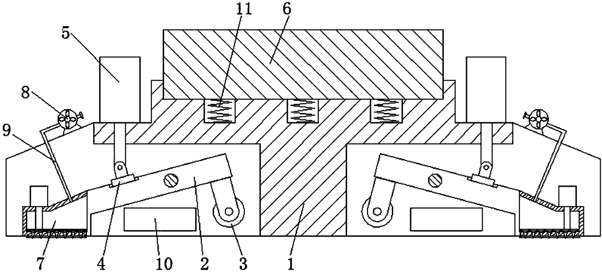
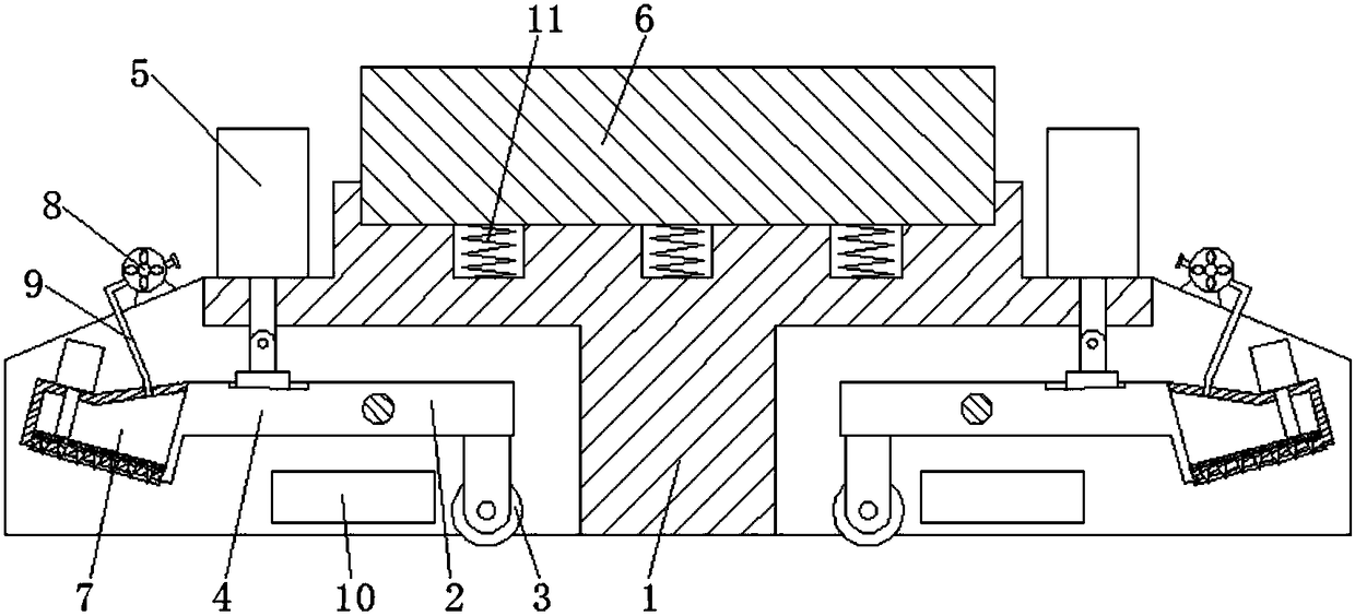
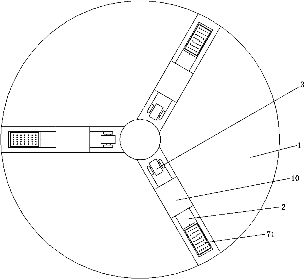
[0023] refer to Figure 1-4 , a mounting base for a robot, comprising a base body 1 with a disc structure, a mounting plate 6 is connected to the center of the top surface of the base body 1, a slot is provided on the top surface of the base body 1, and the mounting plate 6 is embedded in the In the groove, and the side of the mounting plate 6 is in sliding contact with the side of the socket, and the bottom surface of the socket is provided with a plurality of blind holes distributed in an array, and shock-absorbing springs 11 are respectively placed in the blind holes, and the two ends of the shock-absorbing spring 11 Respectively connected to the bottom surface of...


PUM


Abstract

The invention discloses a mounting base for a robot. The mounting base comprises a base body with a disc structure, wherein the a mounting plate is connected with the center of the top surface of thebase body; three notches which are distributed in an array are formed in the bottom surface of the base body, swing rods are rotationally connected with the side surfaces of the notches respectively,the bottoms of the ends, located on the inner sides of the notches, of the swing rods are connected with rollers respectively, the tops, far away from the rollers, of the swing rods are provided withsliding grooves respectively, and sliding blocks are movably connected in the sliding grooves; oil cylinders located above the sliding blocks are arranged on the top surface of the base body, the piston rod ends of the oil cylinders penetrate through the top wall of the base body to be connected with the tops of the sliding blocks, and the ends, located on the outer sides of the notches, of the swing rods are connected with fixing assemblies respectively; and vacuum air pumps are arranged on one side of the top surface of the base body. The mounting base is reasonable in structure and convenient to use, the movement and positioning of the mounting base are facilitated, the mounting base can adapt to different ground surfaces due to the fact the different fixing modes are adopted, the stability of the mounting base is enhanced, and the robot can be kept stable during work.

Description

technical field [0001] The invention relates to the technical field of robots, in particular to a mounting base for a robot. Background technique [0002] Robot is a common name for automatic control machines. Automatic control machines include all machines that simulate human behavior or thoughts and simulate other creatures (such as robot dogs, robot cats, etc.). In contemporary industry, robots refer to man-made machine devices that can automatically perform tasks , to replace or assist human work. [0003] However, the existing robot installation bases have some disadvantages during use, that is, the installation bases are generally placed directly on the ground, because in various working environments, the surface conditions of the ground are different, such as mud floors, tile floors, Glass ground, metal ground, and inclined ground, etc., in these specific environments, if the installation base is placed directly on the ground, it is easy to shift during the working p...

Claims


Application Information

Patent Timeline
Patent Type & Authority Applications(China)
IPC IPC(8): B25J9/00
CPCB25J9/0009
Inventor 靳津
Owner 天津朗硕机器人科技有限公司
Why Eureka
Try Eureka