Endoprosthesis having foot extensions

a technology of endoprosthesis and foot extension, which is applied in the field of endoprosthesis manufacturing, can solve the problems of not appearing as well under fluoroscopy, difficulty in properly placing the endoprosthesis within the vessel, and difficulty in accessing the intended deployment site by a physician, and achieves the effect of changing the stiffness of the endoprosthesis

Inactive Publication Date: 2007-01-25
ABBOTT LAB INC
View PDF99 Cites 63 Cited by
  • Summary
  • Abstract
  • Description
  • Claims
  • Application Information

AI Technical Summary

Benefits of technology

[0016] Preferably, the connection location between the longitudinally adjacent annular elements includes the foot extension. By providing the connection location at the base portion of the foot extension, the apices proximate a side of the first annular element generally can be arranged circumferentially out of alignment, or less than 180 degrees out of phase, with the apices proximate a facing side of the second annular element. The connection location can be defined by an overlapping pattern between the longitudinally adjacent annular elements, such as the base of a foot extension on one annular element and a corresponding apex on the other annular element. Alternatively, the connection location can include a connector extending between the annular elements. The connector can be a straight member or a shaped member, with opposites ends circumferentially either in or out of alignment, as desired. In a preferred embodiment, the connector has an L-shape, with one leg longer than the other leg. It is further contemplated that the connector may be partially or fully constructed of a bioabsorbable material, wherein after deployment within a vessel, the bioabsorbable component of the connector is absorbed thereby changing the stiffness of the endoprosthesis. In a preferred embodiment, a plurality of connection locations are provided between the adjacent annular elements, with a foot extension provided at some or all of the connection locations. The plurality of foot extensions can all extend in the same circumferential direction, or can be arranged to extend in opposing circumferential directions.

Problems solved by technology

Additionally, the intended deployment site may be difficult to access by a physician and often involves traversing the delivery system through the tortuous pathway of the anatomy.
An additional problem with existing endoprosthesis designs is the difficulty in properly placing the endoprosthesis within a vessel prior to deployment of the endoprosthesis.
Current endoprosthesis designs have thinner struts that utilize less radiopaque material and therefore do not appear as well under fluoroscopy.
A shortcoming of present designs is that many are very difficult to manufacture and therefore lead to increased costs.
Also, due to size limitations of the radiopaque material used, the markers do not provide sufficient visibility for precise placement.
Another limitation of current endoprosthesis designs is their unsuitability for materials with high elastic limits such as bioabsorbable polymers.
The expansion of endoprosthesis devices such as stents generally relies on the plastic deformation of the stent material and typical stent designs do not undergo enough strain during expansion to plastically deform bioabsorbable polymers.
This can result in excessive recoil of the stent and sub-optimal apposition of the stent against the vessel wall.

Method used


Image

  • Endoprosthesis having foot extensions
  • Endoprosthesis having foot extensions
  • Endoprosthesis having foot extensions

Examples


Embodiment Construction

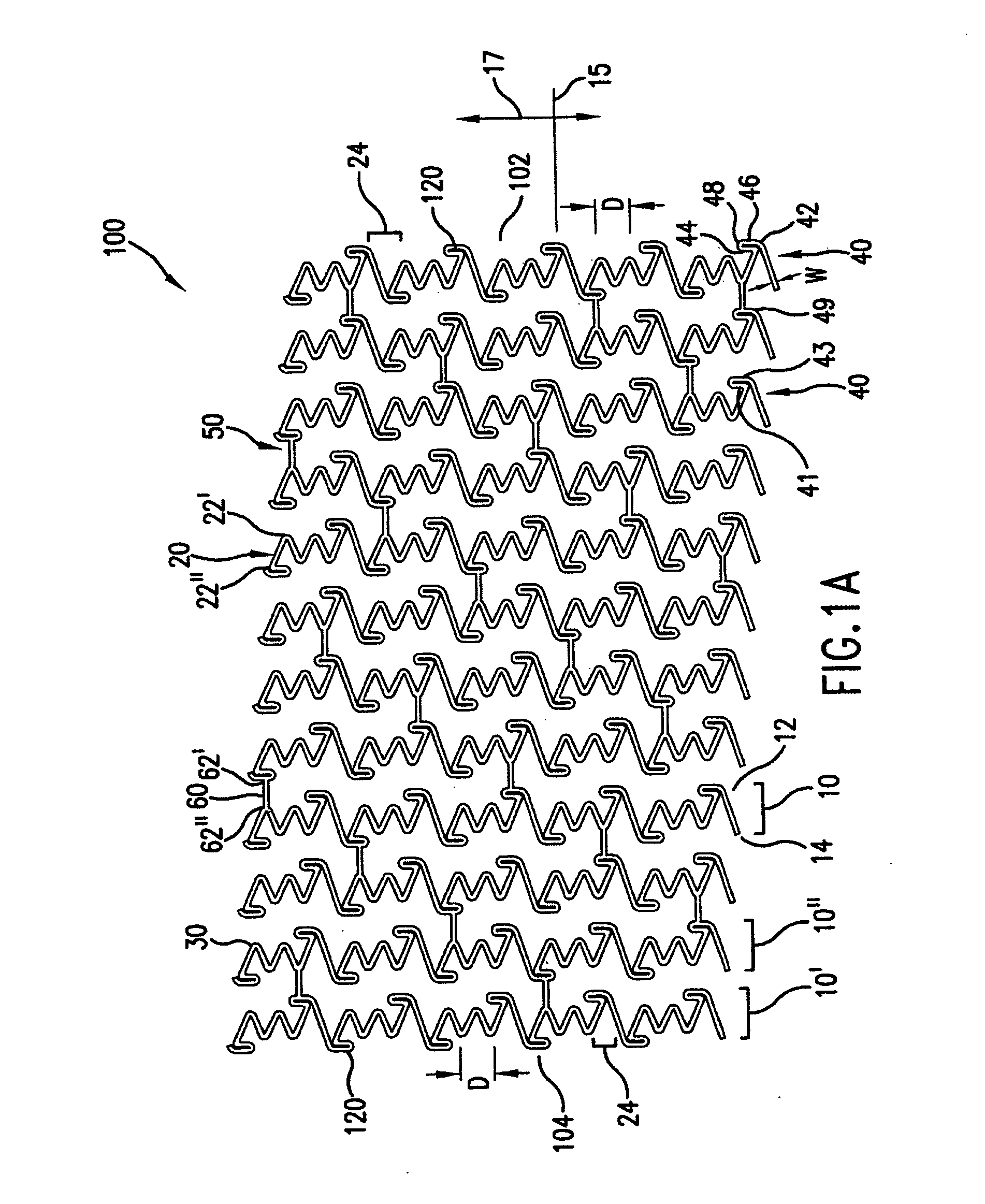
[0039] In accordance with the present invention, an endoprosthesis is provided for delivery within a body lumen of a human or animal. The endoprosthesis can include, but is not limited to, stents, grafts, valves, occlusive devices, trocars, aneurysm treatment devices, or the like. The endoprosthesis of the present invention can be configured for a variety of intralumenal applications, including vascular, coronary, biliary, esophageal, urological, gastrointestinal or the like.

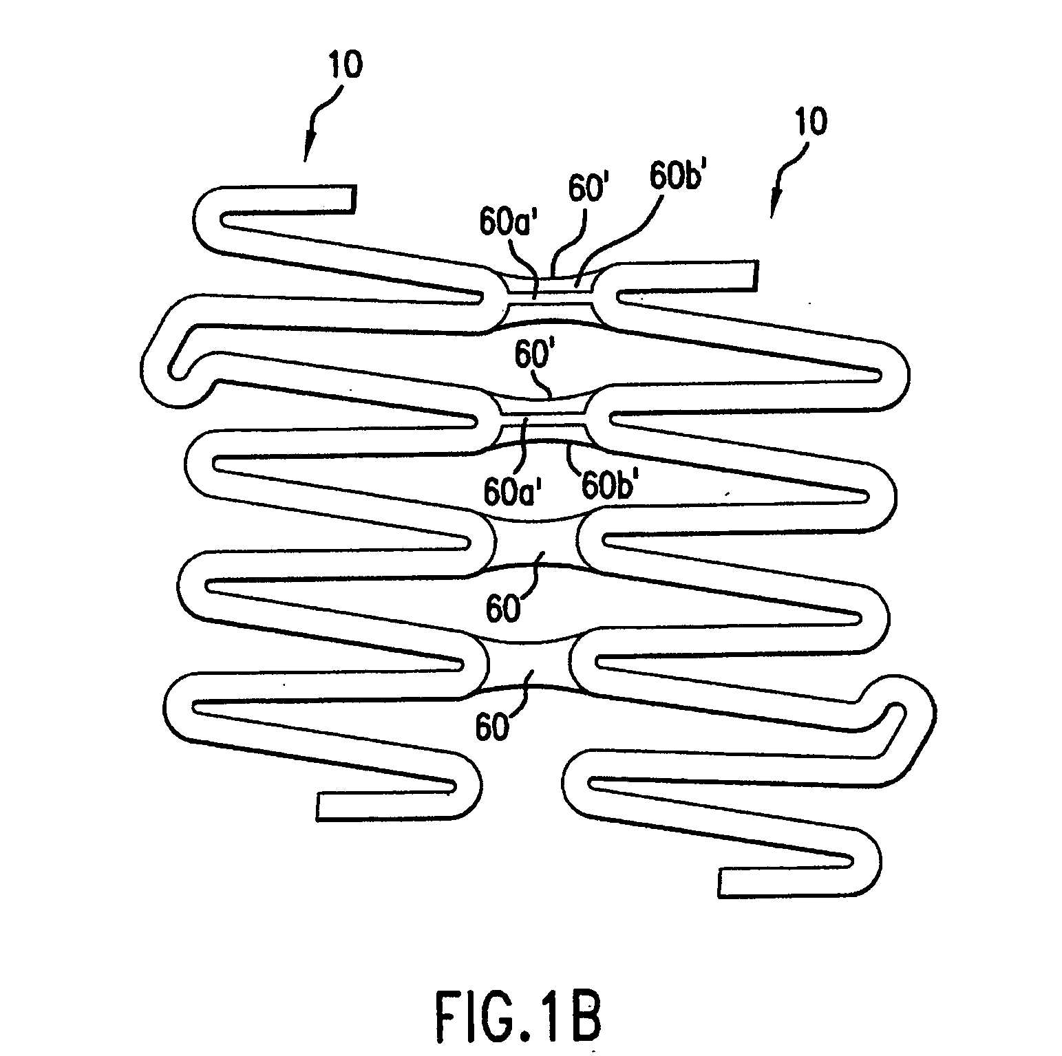
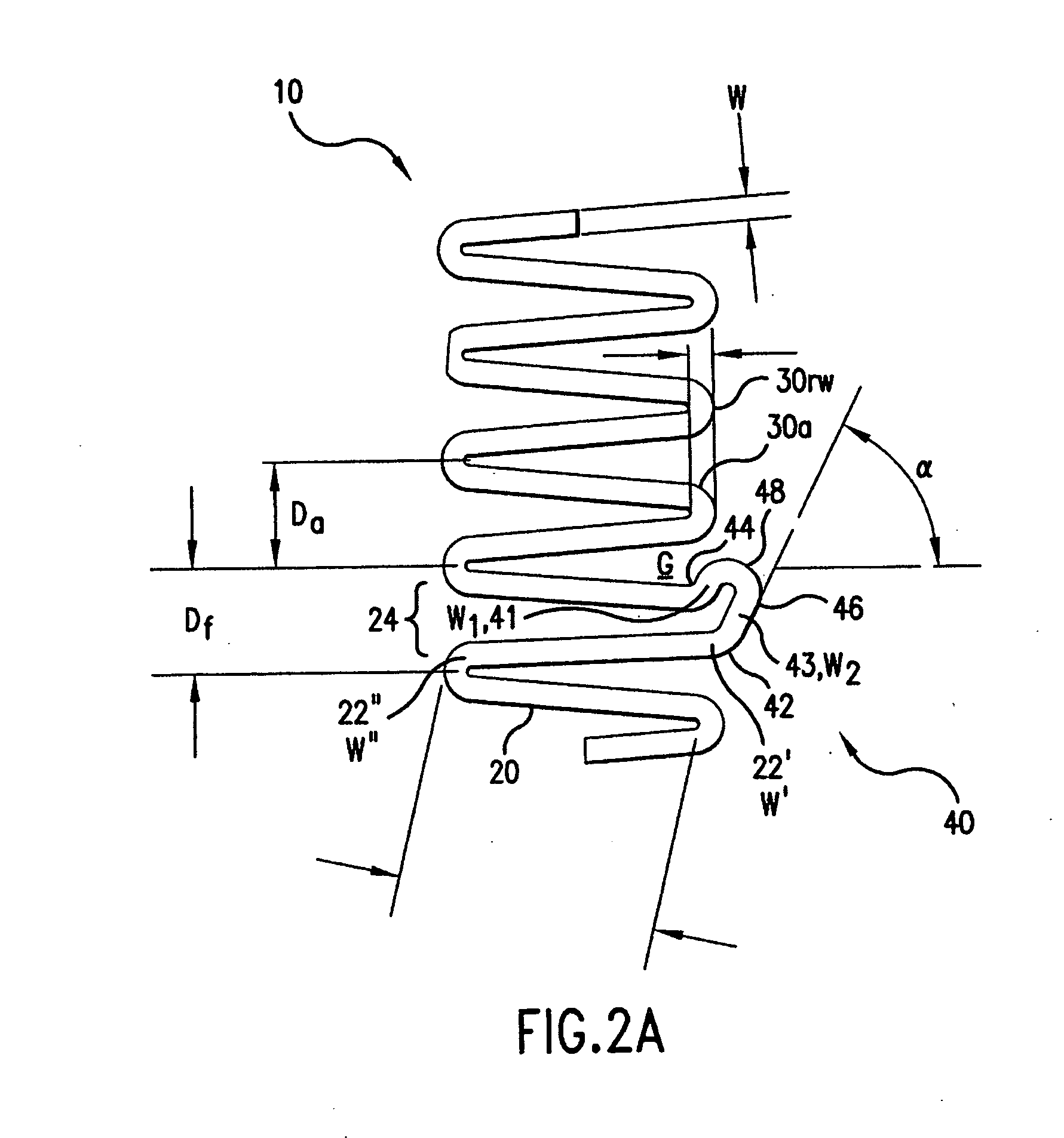
[0040] Generally, the endoprosthesis of the present invention includes a first set of interconnected strut members defining a first annular element, wherein each strut member of the first annular element include a first end and a second end. The endoprosthesis also includes a foot extension extending between a pair of circumferentially adjacent strut members. As described further below, the foot extension has a first foot portion extending circumferentially from the first end of one of the circumferentially-adj...


PUM


Abstract

Endoprosthesis, such as a stent, includes at least one annular element defined by a first set of strut members interconnected to define apices proximate opposite sides of the annular element. The annular element further includes a foot extension extending between at least one pair of circumferentially-adjacent strut members. The foot extension has first and second foot portions extending circumferentially from corresponding ends of the circumferentially-adjacent strut members, and are contoured to provide at least two areas of flexure. The first and second foot portions are joined at a toe portion of the foot extension, and define a circumferentially-directed apex between the pair of circumferentially-adjacent strut members. Preferably, at least one or more additional annular elements, each defined by interconnected strut members, are provided. The annular elements are generally expandable between a delivery configuration and a deployed configuration. The annular elements are longitudinally aligned and connected at connection locations with connectors, wherein at least one of the connectors is constructed of a bio-absorbable material.

Description

CROSS REFERENCE TO RELATED APPLICATIONS [0001] The present application is a continuation-in-part of application Ser. No. 11 / 228,621 which is a continuation-in-part of application Ser. No. 10 / 992,976 which is a continuation-in-part of application Ser. No. 10 / 430,644, the entireties of which are hereby incorporated by reference. The present application claims priority to U.S. Provisional Application Ser. No. 60 / 659,499 filed Jun. 30 ,2005 the entirety of which is hereby incorporated by reference.FIELD OF THE INVENTION [0002] The present invention relates to a method of manufacturing an endoprosthesis for delivery and deployment within a body vessel of a human or animal. More particularly, the invention relates to a stent including at least one annular element having one or more foot extensions for improved performance characteristics and at least one radiopaque marker feature disposed in a portion of the endoprosthesis. BACKGROUND OF THE INVENTION [0003] Stents, grafts and a variety o...

Claims


Application Information

Patent Timeline
Patent Type & Authority Applications(United States)
IPC IPC(8): A61F2/28
CPCA61F2/91A61F2/915A61F2002/91508A61F2002/91525A61F2002/91533A61F2230/0054A61F2002/91558A61F2002/91591A61F2250/0098A61F2220/0041A61F2002/91541
Inventor YOUNG, EUGENEBORG, RUSSTRASK, DAVIDYRIBARREN, TRAVIS RICHARDELI, ERIK
Owner ABBOTT LAB INC
Why Eureka
Try Eureka