Beat extraction apparatus and method, music-synchronized image display apparatus and method, tempo value detection apparatus, rhythm tracking apparatus and method, and music-synchronized display apparatus and method

a technology of image display and beat extraction, which is applied in the field of beat extraction apparatus and method, music-synchronized image display apparatus and method, rhythm tracking apparatus and method, etc., can solve the problems of large amount of calculations, inability to track a piece of music in real time, and inability to extract beats accurately, etc., and achieve the effect of comparatively easy obtention of beat extraction signals

Inactive Publication Date: 2007-02-01
SONY CORP
View PDF12 Cites 45 Cited by
  • Summary
  • Abstract
  • Description
  • Claims
  • Application Information

AI Technical Summary

Benefits of technology

[0030] According to an embodiment of the present invention, with respect to a so-called sampling sound source, it is also possible to obtain a beat extraction signal compar

Problems solved by technology

In the former technology for performing analysis in regions of time, rhythm and a time waveform do not always coincide with each other, and therefore, in essence, the drawback thereof is extraction accuracy.
In the latter technology for performing analysis in regions of frequency, data of all the intervals need

Method used


Image

  • Beat extraction apparatus and method, music-synchronized image display apparatus and method, tempo value detection apparatus, rhythm tracking apparatus and method, and music-synchronized display apparatus and method
  • Beat extraction apparatus and method, music-synchronized image display apparatus and method, tempo value detection apparatus, rhythm tracking apparatus and method, and music-synchronized display apparatus and method
  • Beat extraction apparatus and method, music-synchronized image display apparatus and method, tempo value detection apparatus, rhythm tracking apparatus and method, and music-synchronized display apparatus and method

Examples


second embodiment

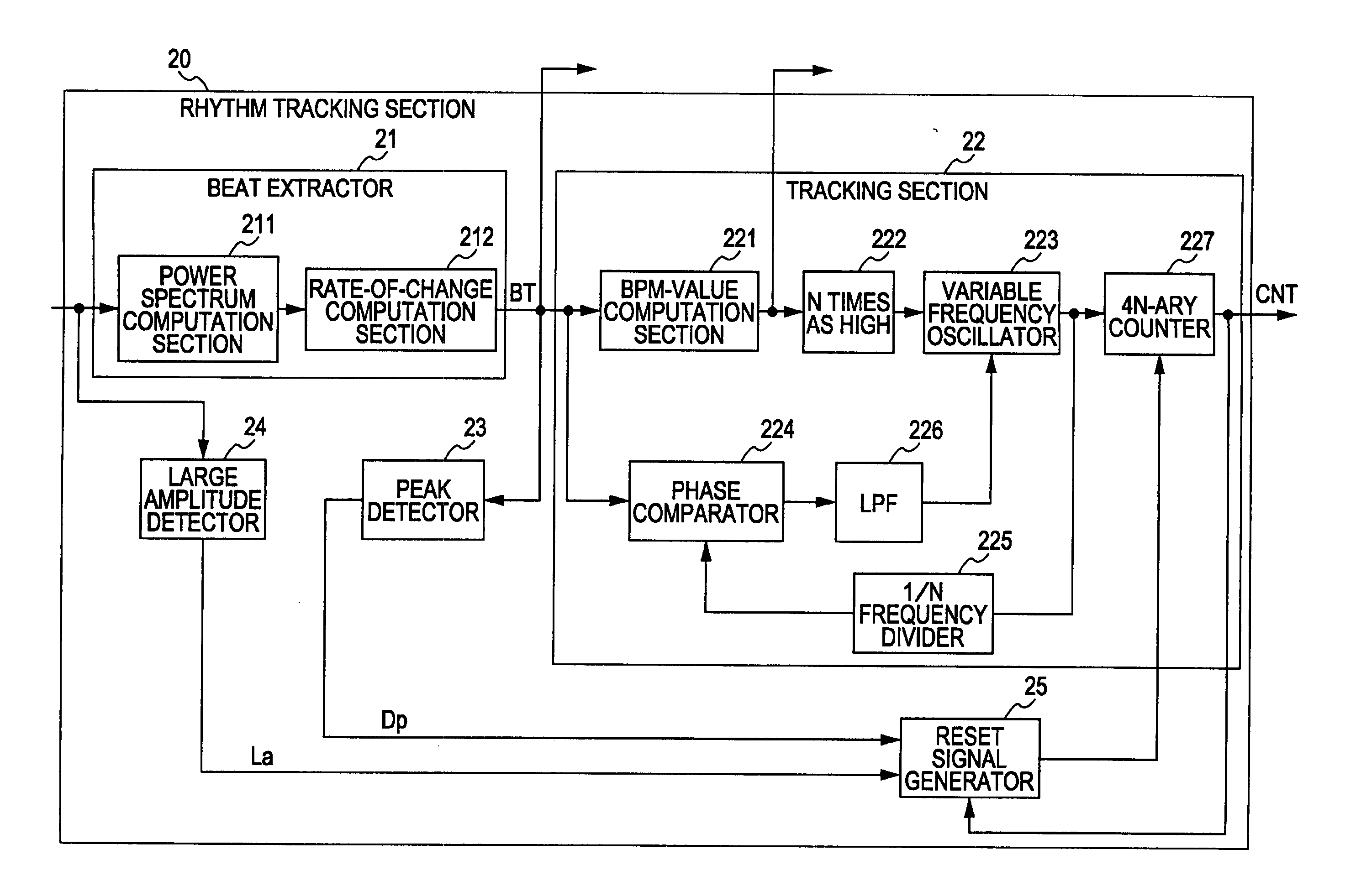
[0119] [Second Embodiment of the Rhythm Tracking Apparatus]

[0120] When the rhythm tracking section 20 of FIG. 4 is actually operated, the PLL circuit has contradictory properties such that, when the synchronization pull-in range is increased, phase jitter during steady time increases, and conversely, when phase jitter is to be decreased, the pull-in range of the PLL circuit becomes narrower.

[0121] When these properties apply to the rhythm tracking section 20, if the range of the BPM value, in which rhythm tracking is possible, is increased, jitter of the oscillation output clock during steady time increases by the order of, for example, +several BPM, and a problem arises in that the fluctuation of a tracking error increases. On the contrary, when setting is performed so that phase jitter of a tracking error is to be decreased, the pull-in range of the PLL circuit becomes narrower, and a problem arises in that the range of the BPM value, in which tracking is possible, becomes narrow...

third embodiment

[0127] [Third Embodiment of the Rhythm Tracking Section 20]

[0128] The third embodiment of the rhythm tracking apparatus is a case in which a piece of music to be input (played back) is unknown and an offline process is not possible. In the third embodiment, in the rhythm tracking section 20 of FIG. 4, initially, the pull-in range of the PLL circuit is set wider. Then, after rhythm tracking begins to be stabilized, the pull-in range of the PLL circuit is set again to be narrower.

[0129] As described above, in the third embodiment, the above-described problem of phase jitter can be effectively solved by using a technique for dynamically changing a parameter of the pull-in range of the PLL circuit of the tracking section 22 of the rhythm tracking section 20.

[0130] [Example of Application Using Output of the Rhythm Tracking Section 20]

[0131] In this embodiment, various applications are implemented by using output signals from the rhythm tracking section 20, that is, the beat component ...


PUM


Abstract

A music-synchronized display apparatus includes a beat extractor configured to detect a portion in which a power spectrum in a spectrogram of an input music signal greatly changes and to output a detection output signal that is synchronized in time to the changing portion in synchronization with the input music signal; a tempo value estimation section configured to detect the self-correlation of the detection output signal from the beat extractor and to estimate a tempo value of the input music signal; a variable frequency oscillator in which an oscillation center frequency is determined on the basis of the tempo value from the tempo value estimation section and the phase of the output oscillation signal is controlled on the basis of a phase control signal; a phase comparator; a beat synchronization signal generation and output section; an attribute information storage section; an attribute information obtaining section; and a display information generator.

Description

CROSS REFERENCES TO RELATED APPLICATIONS [0001] The present invention contains subject matter related to Japanese Patent Application JP 2005-216786 filed in the Japanese Patent Office on Jul. 27, 2005, the entire contents of which are incorporated herein by reference. BACKGROUND OF THE INVENTION [0002] 1. Field of the Invention [0003] The present invention relates to an apparatus and a method for extracting the beat of the rhythm of a piece of music being played back while an input music signal is being played back. Furthermore, the present invention relates to an apparatus and a method for displaying an image synchronized with a piece of music being played back by using a signal synchronized with an extracted beat. Furthermore, the present invention relates to an apparatus and a method for extracting a tempo value of a piece of music by using a signal synchronized with a beat extracted from the piece of music being played back. Furthermore, the present invention relates to a rhythm...

Claims


Application Information

Patent Timeline
IPC IPC(8): G10H7/00G10L25/51
CPCG10H1/368G10H2210/076G10H2250/235G10H2240/325G10H2220/011
Inventor YAMASHITA, KOSEI
Owner SONY CORP
Why Eureka
Try Eureka