Optical fiber connector cleaner, and method of cleaning optical fiber connector connection surface

a technology cleaners, which is applied in the direction of carpet cleaners, instruments, photosensitive materials, etc., can solve the problems of reducing the transmission performance, reducing the cleaning efficiency of optical fiber connectors incorporated in equipment, and not providing a tool with superior cleaning properties suitable for practical use, etc., to achieve the effect of superior operability and cleaning

Active Publication Date: 2007-02-01
SEIKOH GIKEN
View PDF10 Cites 33 Cited by
  • Summary
  • Abstract
  • Description
  • Claims
  • Application Information

AI Technical Summary

Benefits of technology

[0035] According to the present invention, an optical fiber connector cleaner is provided having superior operability and cleani

Problems solved by technology

Accordingly, when such a connector is detached grease or dust or the like can become stuck to the end surface of the optical fiber connector which leads to a decrease in transmission performance.
However, a connector that is on the insertion and attachment side, that is to say the side that is inserted (male side), is relatively easy to clean as the end surface thereof is exposed, while the insert receive side (female side) of a connector incorporated in an equipment is difficult to clean, because a connecting adapter is attached to the female side of the connector and the end surface to be cleaned is far back from the adapter.
H9-285766) have been proposed, however these do not provide a tool with sup

Method used


Image

  • Optical fiber connector cleaner, and method of cleaning optical fiber connector connection surface
  • Optical fiber connector cleaner, and method of cleaning optical fiber connector connection surface
  • Optical fiber connector cleaner, and method of cleaning optical fiber connector connection surface

Examples


first embodiment

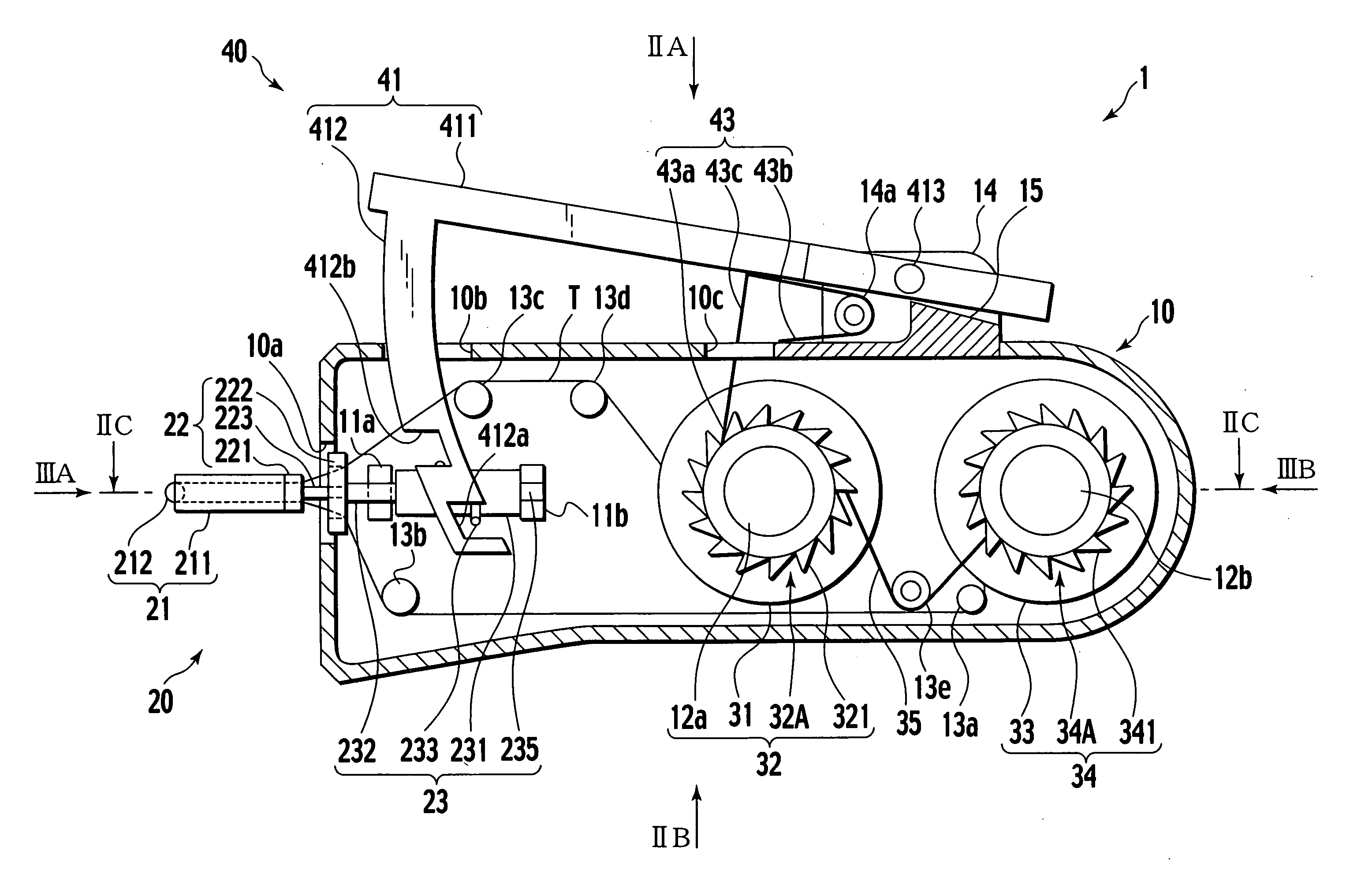
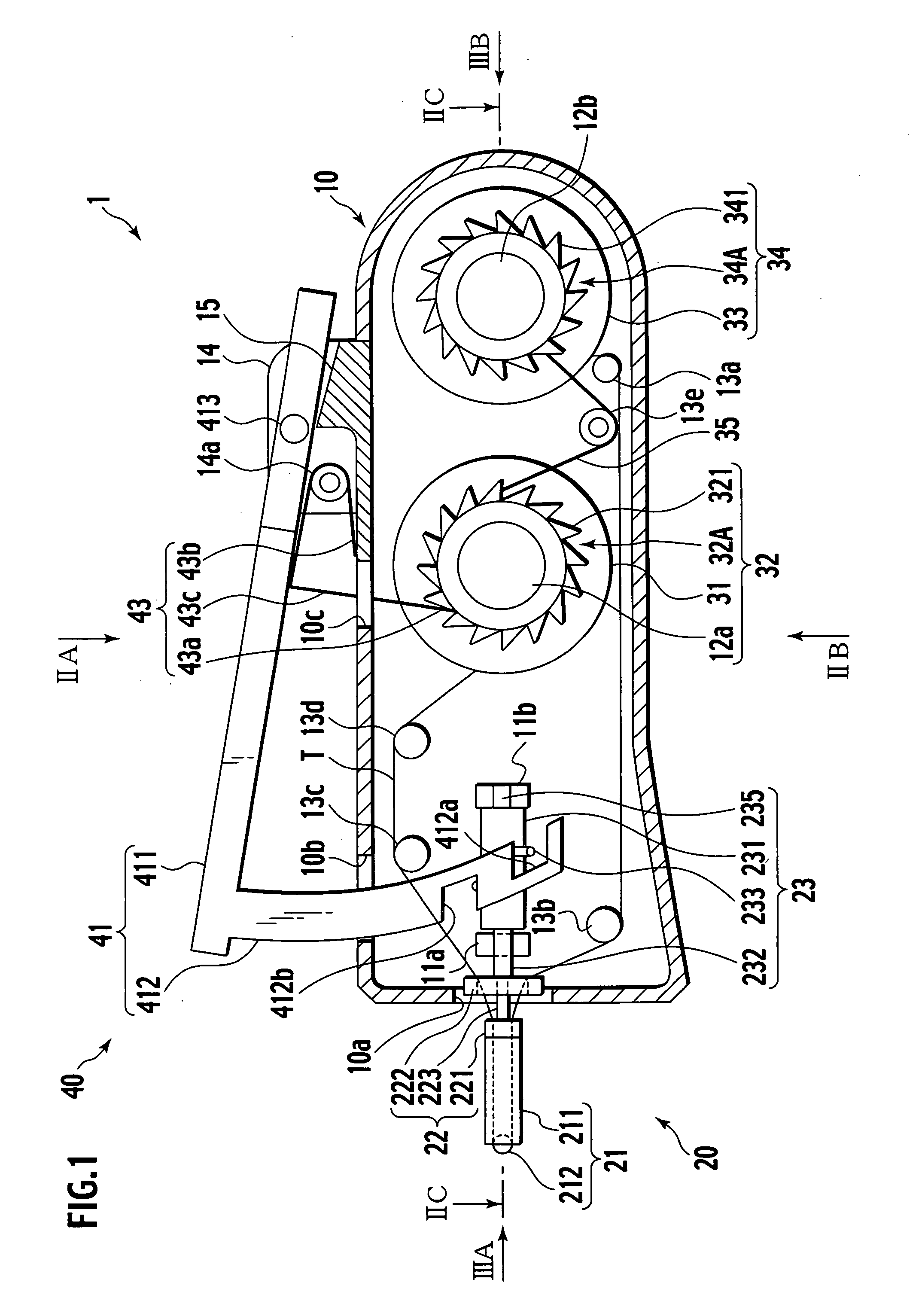
[0065] Referring to FIG. 1, the optical fiber connector cleaner 1 comprises a long, extended housing 10, cleaning means 20 attached to one end in the longitudinal direction of the housing 10, cleaning tape winding means 32 and cleaning tape delivery means 34 both disposed inside the housing 10, and transmission means 40, the operating part of which protrudes outside the housing 10.

[0066] The housing 10 further provides openings 10a, 10b and 10c passing through the outer wall and arranged on the periphery thereof. The housing 10 also includes bearings 11a and 11b positioned corresponding to the cleaning means 20. The housing 10 includes shafts 12a and 12b positioned respectively, corresponding to the winding means 32 and the delivery means 34. The housing 10 houses posts 13a, 13b, 13c and 13d for guiding the cleaning tape T, and a bearing 13e that comprises the center of oscillating rotation of a torsion spring 35 that serves as a link for conveying rotation of the winding means 32 ...

first modification

[0094]FIG. 8 shows another embodiment of the roller 212 mounted at the end of the hollow bar-like member 211 of the cleaning section 21 of the first embodiment.

[0095] The barrel shaped roller shown in FIG. 8 (a) can be used for most, ordinary connector ferrule end surfaces. The drum shaped roller shown in FIG. 8 (b) is especially suitable for use for a ferrule end surface of an angled-physical-contact (APC) polished optical connector in a standard connector.

[0096] The roller shown in FIG. 8 (c) with whirl shaped belt like protrusions disposed on the roller surface and the roller shown in FIG. 8 (d) with disc shaped protrusions disposed on the roller surface at predetermined intervals are suitable for use when soiling is adhered strongly to the connector surface.

second modification

[0097]FIG. 9 shows another embodiment of the guide 22 of the first embodiment.

[0098]FIG. 9 (a) shows a guide member 22A having cone shape with the head cut off, disposed at the rear end of the bar-like member 211 of the cleaning section 21. FIG. 9 (b) is a perspective view of the guide member 22A.

[0099] Through holes 224A and 225A having a flat rectangular cross-section for guiding the tape are disposed on the guide member 22A. These guide holes 224A and 225A are disposed at an inclination in relation to the axis of the guide member 22A such that they are positioned mutually separating toward the tape delivery side and the tape winding side, from the rear end of the bar-like member of the cleaning means. Accordingly, even if twisting is applied to the cleaning tape due to the rotation of the cleaning section 21, an increase in friction resistance occurring when the cleaning tape is running can be prevented.

[0100]FIG. 9 (c) shows another guide member 22B having a cone shape with c...


PUM


Abstract

An optical fiber connector cleaner (1) comprises a housing (10), a winding means (32) and a delivery means (34) for a cleaning tape (T) which are disposed in the housing, a cleaning means (20) having a bar-like cleaning section (21) projecting outwardly of the housing, on the front-end of the cleaning section the cleaning tape delivered from the delivery means being movably mounted under tension in an exposed state, the front-end of the cleaning section being brought into contact with the end surface of an optical fiber connector to thereby clean the end surface, a cleaning section rotating means (23) coaxially connected to the cleaning section in the housing and rotatably supported with respect to the housing; and a transmission means (40) which rotates the winding means and the cleaning section rotating means substantially simultaneously in a predetermined direction through a predetermined angle and then reverses the cleaning section rotating means to its original position.

Description

TECHNICAL FIELD [0001] The present invention relates to a cleaner used for cleaning the ferrule end surface (connection surface) of an optical fiber connector incorporated in optical communications equipment and the like. More specifically, the present invention relates to a cleaner suitable for cleaning the ferrule end surface of an optical fiber connector when mounted in an adapter. BACKGROUND TECHNOLOGY [0002] An optical fiber connector incorporated in equipment used in connection with optical communications equipment is frequently connected and detached. Accordingly, when such a connector is detached grease or dust or the like can become stuck to the end surface of the optical fiber connector which leads to a decrease in transmission performance. When the optical fiber connector is attached or detached the ferrule end surface must be cleaned. [0003] However, a connector that is on the insertion and attachment side, that is to say the side that is inserted (male side), is relativ...

Claims


Application Information

Patent Timeline
IPC IPC(8): B08B7/00G02B6/38
CPCB08B11/00G02B6/3866G02B6/381G02B6/36G02B6/38
Inventor KIDA, TAKAHISATAGUCHI, KATSUHISA
Owner SEIKOH GIKEN
Why Eureka
Try Eureka