Seal assembly for fuel fill pipes

a fill pipe and assembly technology, applied in the direction of liquid handling, transportation and packaging, packaging goods types, etc., can solve the problem of reducing the hydrocarbon removal capacity of the hydrocarbon canister, and achieve the effect of reducing the air entrainment with the fuel during refueling, reducing the volume of fumes, and reducing the air admitted

Active Publication Date: 2007-02-01
ILLINOIS TOOL WORKS INC
View PDF8 Cites 16 Cited by
  • Summary
  • Abstract
  • Description
  • Claims
  • Application Information

AI Technical Summary

Benefits of technology

[0012] An advantage of the present invention is providing a seal between a vehicle fuel system fill pipe and a refueling nozzle to reduce air admitted through the fill pipe and thereby decrease air entrainment with the fuel during refueling.
[0013] Another advantage of the present invention is providing a seal between a fill pipe of a vehicle fuel system and a refueling nozzle inserted therein to reduce the volume of fumes escaping untreated from the fuel tank via the fill pipe.
[0014] A further advantage of the present invention is providing a seal between a fill pipe of a vehicle fuel system and a refueling nozzle inserted therein which retards air flow there past during normal refueling conditions, and also provides over-fill and over-pressure relief if over-fill or over-pressure occurs.
[0015] Still another advantage of the present invention is providing a seal between a vehicle fuel system fill pipe and a refueling nozzle inserted therein that does not interfere with known, common refueling procedures and is easy to use.
[0016] Yet another advantage of the present invention is providing a seal between a vehicle system fill pipe and a refueling nozzle inserted therein that can be installed quickly and easily at minimal cost.
[0017] Other features and advantages of the invention will become apparent to those skilled in the art upon review of the following detailed description, claims and drawings in which like numerals are used to designate like features.

Problems solved by technology

Disadvantages experienced with some fuel systems during a refueling operation result from the relatively free airflow that can occur through the fill pipe via the space between the fuel fill pipe and the refueling nozzle outlet tube.
However, since airflow is relatively unrestricted through the fill pipe and post the nozzle, escaping air and hydrocarbons from the tank can follow that path as well, avoiding the vapor outlet system and carbon canister, and being released into the atmosphere untreated.
Accordingly, reducing air entrainment with the fuel during refueling, and thereby reducing hydrocarbon vapors expelled during refueling, reduces the hydrocarbon removal capacity required for the hydrocarbon canister.

Method used


Image

  • Seal assembly for fuel fill pipes
  • Seal assembly for fuel fill pipes
  • Seal assembly for fuel fill pipes

Examples


Embodiment Construction

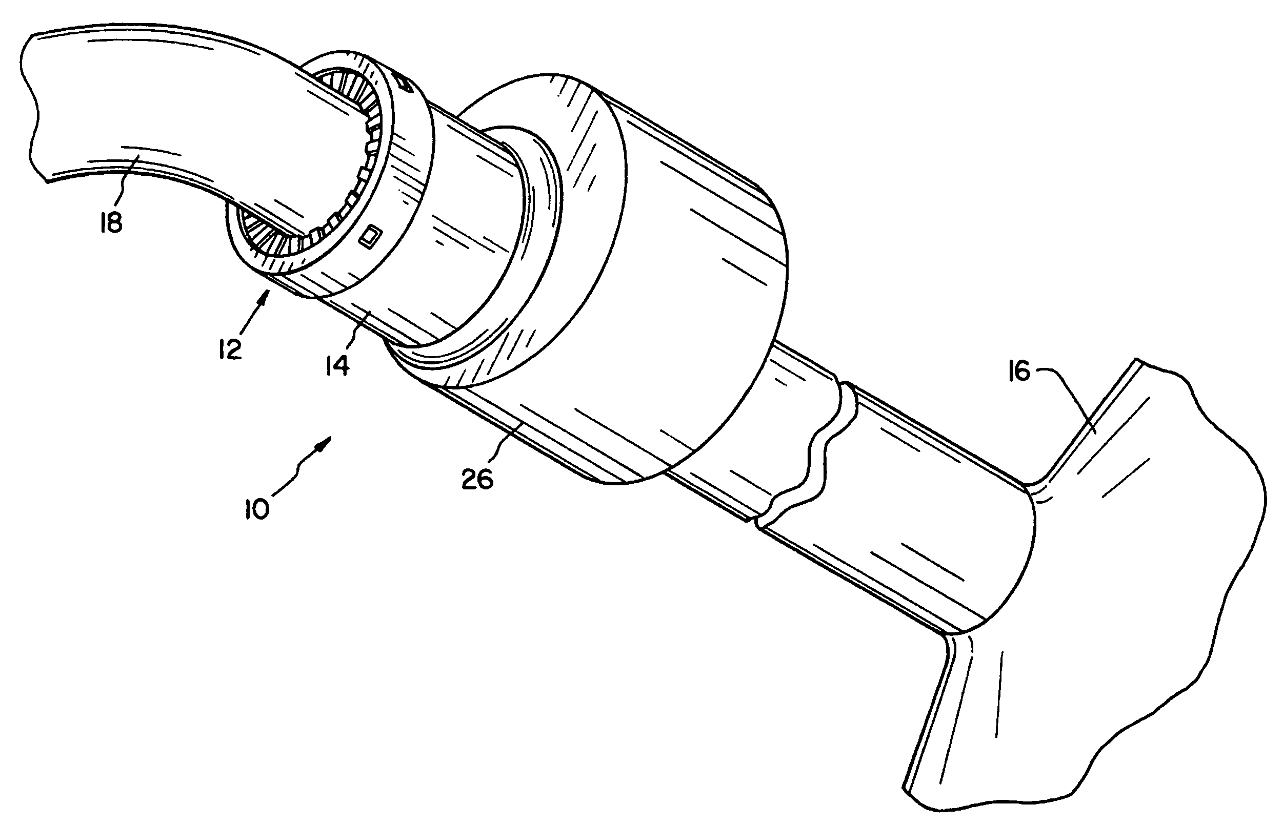
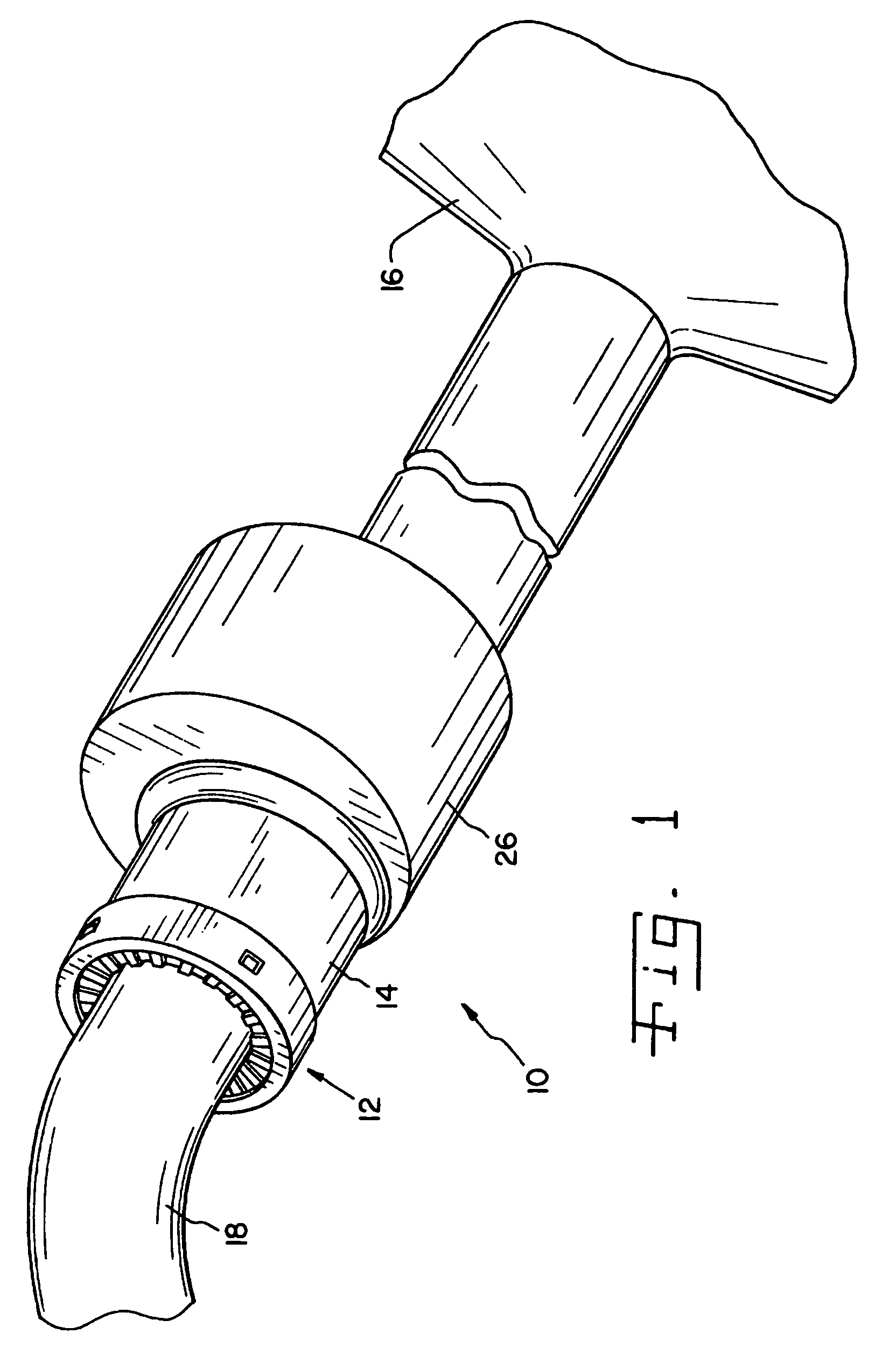
[0023] Referring now more specifically to the drawings and to FIG. 1 in particular, a vehicle fuel system 10 is shown with a seal assembly 12 in accordance with the present invention. Seal assembly 12 is provided at an outer end of a fuel fill pipe 14 leading to a fuel tank 16. As illustrated in FIG. 1, fuel system 10 is undergoing a refueling operation, with a nozzle 18 from a fuel supply pump inserted through seal assembly 12 and into fuel fill pipe 14.

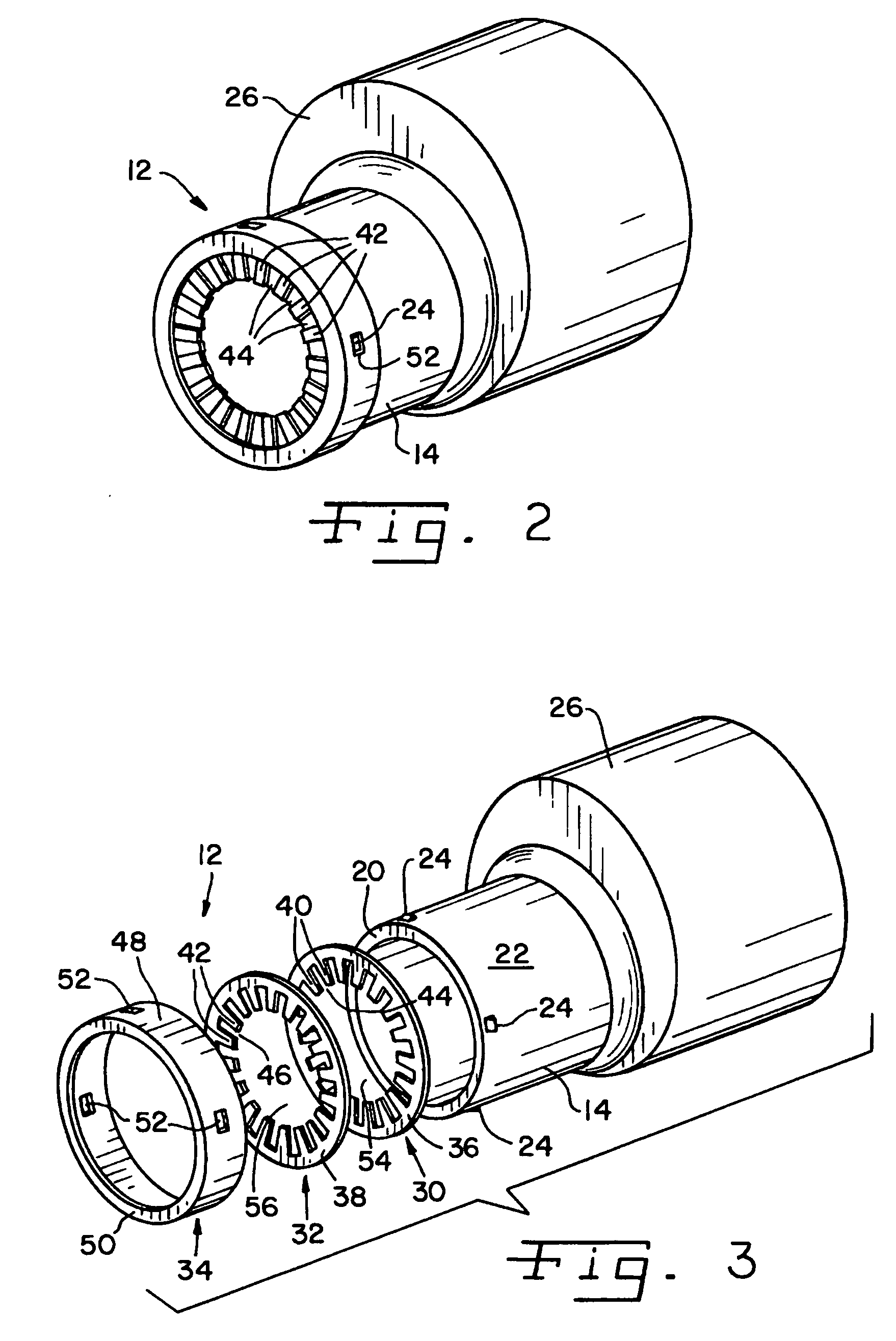
[0024] Fill pipe 14 and fuel tank 16 can be of generally known configuration and made of metal and / or fuel resistant plastics. Seal assembly 12 is attached at a terminal end 20 of fill pipe 14. In the exemplary embodiment shown, an outer surface 22 of fill pipe 14 near terminal end 20 is provided with a plurality of protrusions 24 to cooperate with seal assembly 12 in a manner to be described hereinafter for holding seal assembly 12 against terminal end 20. As known to those skilled in the art, an expansion chamber 26 is provided w...


PUM

PropertyMeasurementUnit
flexibleaaaaaaaaaa
sizeaaaaaaaaaa
diameteraaaaaaaaaa

Abstract

A seal assembly is provided for a fill pipe of a vehicle fuel system to provide a pliable seal between an end of the fuel pipe and a refueling nozzle inserted in the fill pipe.

Description

CROSS-REFERENCE TO RELATED APPLICATIONS [0001] The present regular United States patent application claims the benefits of U.S. Provisional Application Ser. No. 60 / 702,675, filed on Jul. 26, 2005.FIELD OF THE INVENTION [0002] The present invention relates generally to seals and to automobile fuel systems and, more particularly, the invention pertains to a sealing structure or assembly on fuel fill pipe that cooperates with a refueling nozzle inserted in the fill pipe. BACKGROUND OF THE INVENTION [0003] Vehicle fuel systems are known to include a tank for holding fuel and a fuel fill pipe that functions as an inlet for supplying fuel to the tank from a nozzle at a refueling station. Vehicle fuel systems are known to include primary and secondary shutoffs to close the system. [0004] The fuel fill pipe has an opening that can be exposed during refueling to receive the nozzle. Both capless and capped fuel fill pipes are known. An exposed end portion of the fuel fill pipe is of sufficien...

Claims


Application Information

Patent Timeline
Patent Type & Authority Applications(United States)
IPC IPC(8): B65B1/04
CPCB60K2015/0451B60K15/04B60K2015/048
Inventor CISTERNINO, FRANCO A.HAPPEL, BRYAN K.
Owner ILLINOIS TOOL WORKS INC
Why Eureka
Try Eureka