Refrigerant circuit

a refrigerant circuit and circuit technology, applied in the field of refrigerant circuits for vehicles, can solve the problems of reducing the efficiency of the compressor, the pump contains an excessive amount of refrigerant, etc., and achieves the reduction of the amount of filling, the effect of minimizing the cross-section of the conduit and reducing the cost and a weigh

Inactive Publication Date: 2013-02-07
HANON SYST
View PDF6 Cites 6 Cited by
  • Summary
  • Abstract
  • Description
  • Claims
  • Application Information

AI Technical Summary

Benefits of technology

[0024]A cross-section of the conduit and a conduit guidance or bends in the conduit can be calculated for each vehicle, so that no noticeable loss of pressure occurs during the cooling operation, while a defined loss of pressure during the heat pump operation can be obtained for the heating operation.
[0025]In particular, the cross-section of the conduit is smaller than prior art. Accordingly, material for the conduits, and thus a cost and a weight can be minimized. A minimized conduit cross-section also results in a reduction in the amount for filling and a reduced need for refrigerant over the prior art.

Problems solved by technology

A disadvantage of the refrigerant circuit is that no heat exchange with the low pressure side part of the internal heat exchanger in the heat pump operation can occur without significant technical effort since the internal heat exchanger in the heat pump is disposed in the low pressure area of the refrigerant circuit.
Further, the heat pump contains an excessive amount of the refrigerant since a filling amount is determined according to the air conditioner operation.
As a result, suctioning of the refrigerant into the compressor is unavoidable, thereby decreasing an efficiency of the compressor.

Method used


Image

  • Refrigerant circuit
  • Refrigerant circuit
  • Refrigerant circuit

Examples


Embodiment Construction

of EXEMPLARY EMBODIMENTS OF THE INVENTION

[0037]The following detailed description and appended drawings describe and illustrate various exemplary embodiments of the invention. The description and drawings serve to enable one skilled in the art to make and use the invention, and are not intended to limit the scope of the invention in any manner. Equivalent components or components with equivalent effect are shown in the following examples of embodiments with the same reference list number.

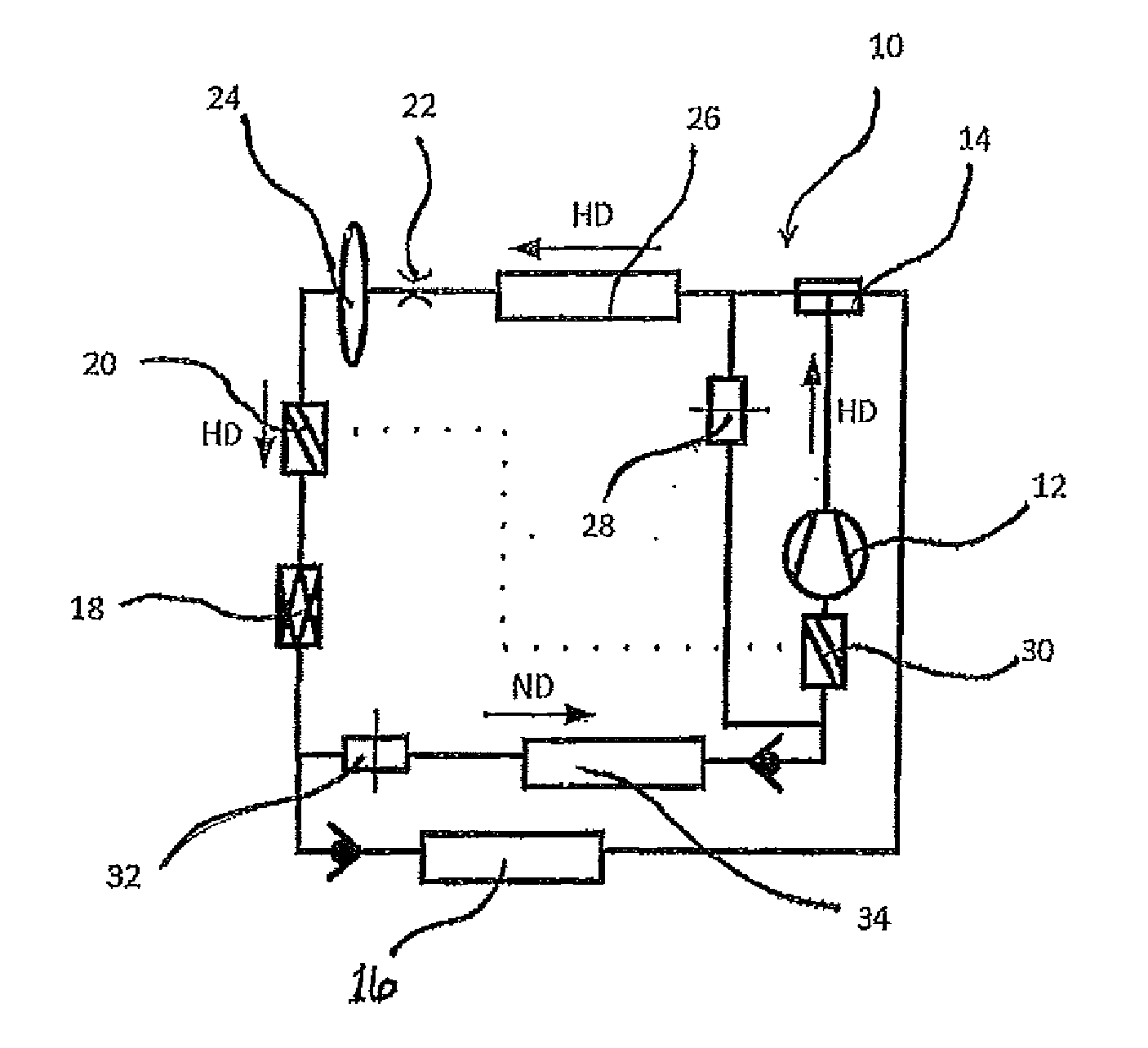
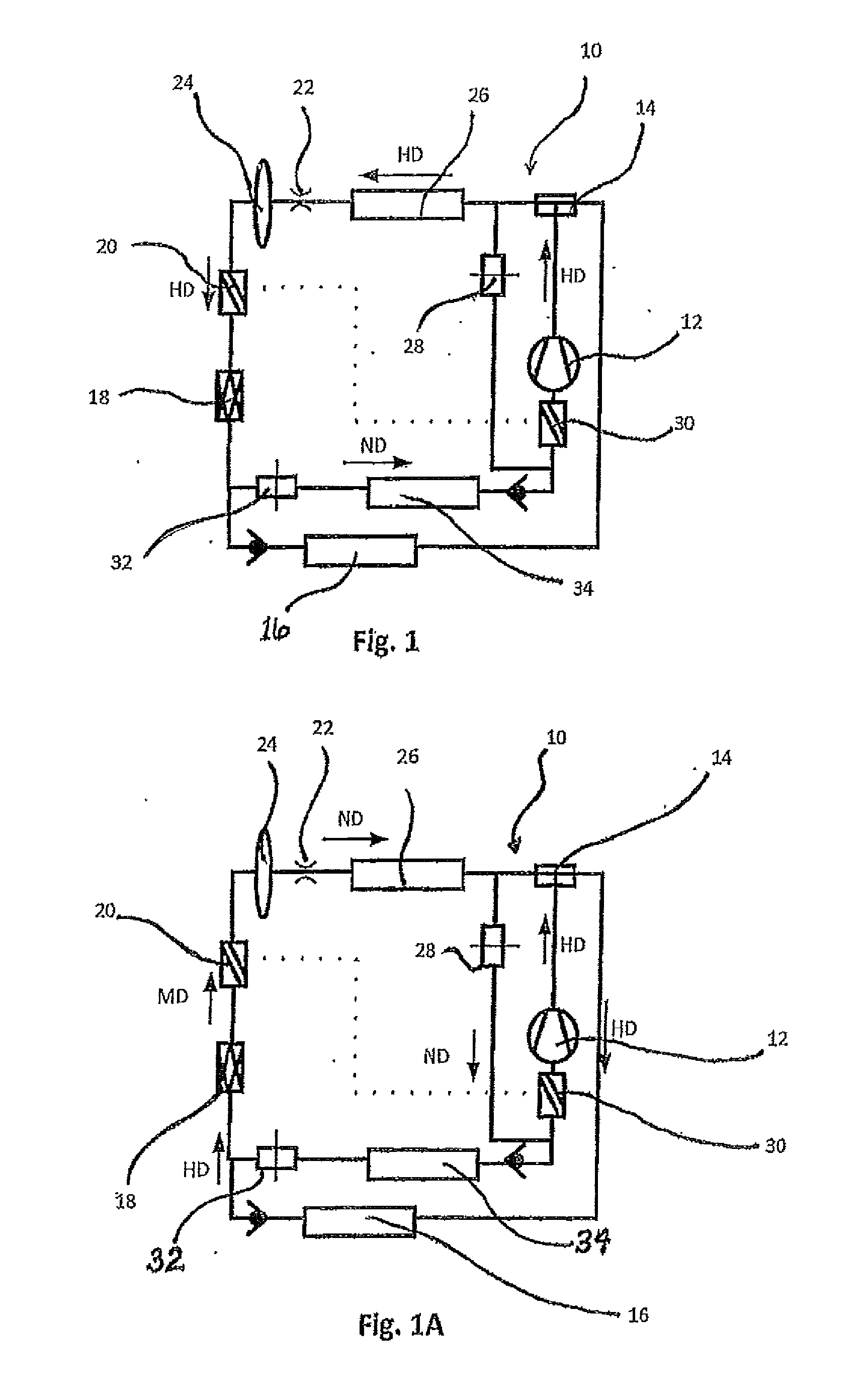
[0038]FIGS. 1 and IA show a schematic presentation of a refrigerant circuit 10 of a vehicle air conditioner according to the present invention. The refrigerant circuit 10 is suitable for both a cooling operation, illustrated in FIG. 1, and a heat pump operation, illustrated in FIG. 1A. During the cooling operation shown in FIG. 1, a refrigerant under high pressure flows out of a compressor 12 through a valve 14, through a condenser / gas cooler 26, and through a metering device 22. As a non-limiting e...


PUM


Abstract

The invention includes a refrigerant circuit for a cooling operation and a heat pump operation. The refrigerant circuit has a high pressure area and a low pressure area, including at least one heat source/heat sink, a compressor, an expansion device, at least one thermal interior space module, and an internal heat exchanger. The internal heat exchanger has a high pressure side part and a low pressure side part, wherein the high pressure side part is disposed between the expansion device and the heat source/heat sink. The invention also includes at least one metering device through which the high pressure side part of the internal heat exchanger is operable during the heat pump operation at a medium pressure level intermediate a pressure level in the high pressure area and a pressure level in the low pressure area of the refrigerant circuit.

Description

CROSS-REFERENCE TO RELATED APPLICATION[0001]This application claims the benefit of German Patent Application No. DE 10 2011 109 506.7 filed Aug. 5, 2011, the entire disclosure of which is hereby incorporated herein by reference.FIELD OF THE INVENTION[0002]The invention involves a refrigerant circuit for a vehicle, and more particularly a refrigerant circuit for a vehicle configured to optimize performance of an internal heat exchanger during a cooling operation and a heat pump operation.BACKGROUND OF THE INVENTION[0003]DE 103 09 779 A1 discloses a double-loop air conditioner in which refrigerant is heated in a heat pump or through a compression of the refrigerant, and is then released to a condenser in an interior space module (hereinafter referred to as the heat register) for heating an inflow of air into an interior space. In addition, heat can be taken from a refrigerant circuit of a motor and directed to the refrigerant through a heat transfer device, or an inflow of air into th...

Claims


Application Information

Patent Timeline
Patent Type & Authority Applications(United States)
IPC IPC(8): F25B41/04F25B49/02
CPCB60H1/32F25B30/00B60H2001/00942F25B41/06B60H1/00907F25B41/00F25B30/02F25B2600/2513F25B41/385F25B41/39F25B41/24
Inventor HEYL, PETERREBINGER, CHRISTIANSCHROEDER, DIRKHAMMER, HANSHOETZEL, MARTIN
Owner HANON SYST
Why Eureka
Try Eureka