High fiber count optical fiber cable with buffer tubes around central strength member

a buffer tube and optical fiber technology, applied in the field of optical fiber communication cables, can solve the problems of increasing the diameter of the cable, reducing the flexibility of the loose tube cable, and disturbing the minimum number of fibers not being accessed, so as to increase the total number of optical fibers, reduce the diameter, and increase the space available

Inactive Publication Date: 2005-03-22
PRYSMIAN COMM CABLES & SYST USA LLC
View PDF31 Cites 26 Cited by
  • Summary
  • Abstract
  • Description
  • Claims
  • Application Information

AI Technical Summary

Benefits of technology

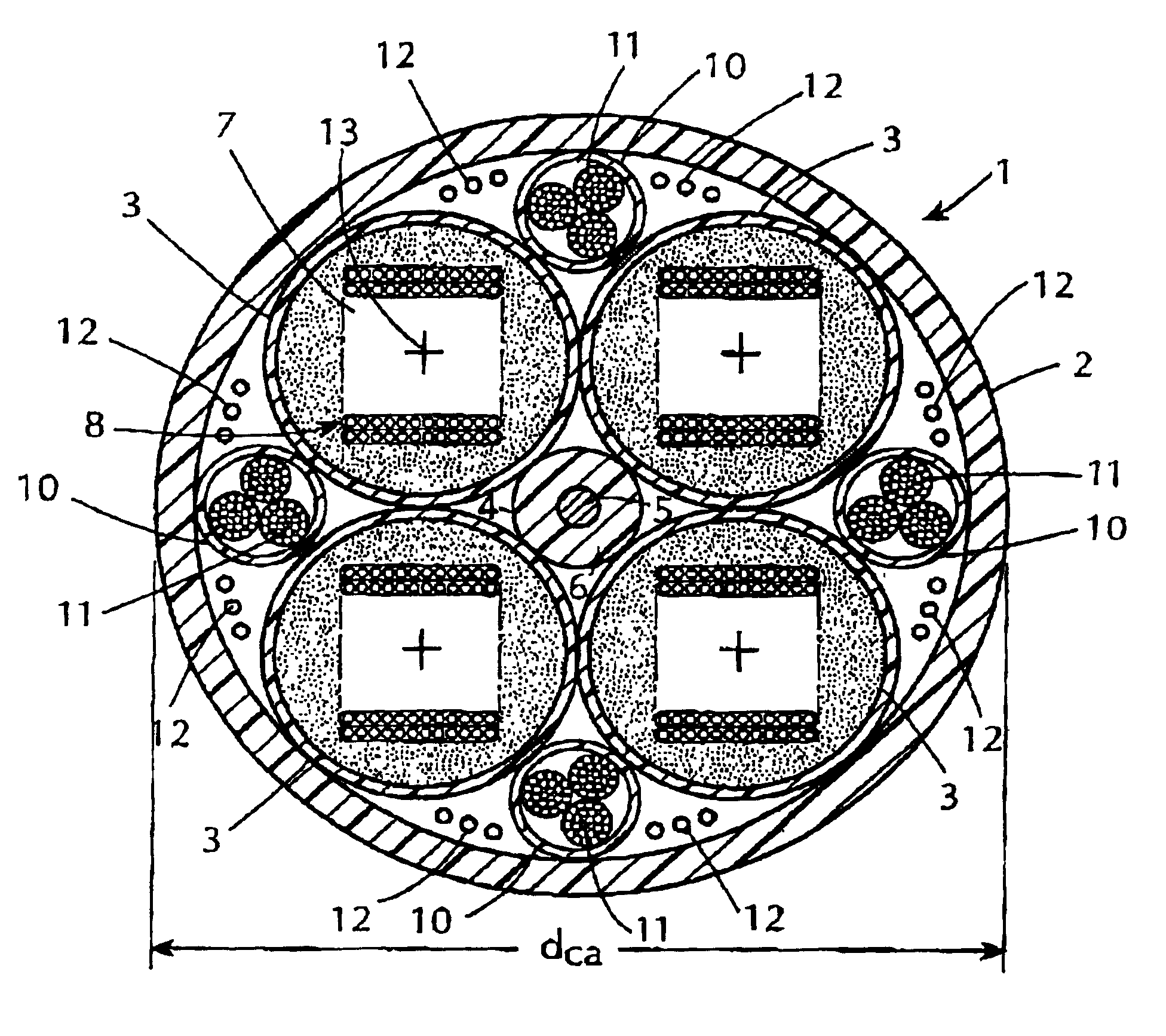
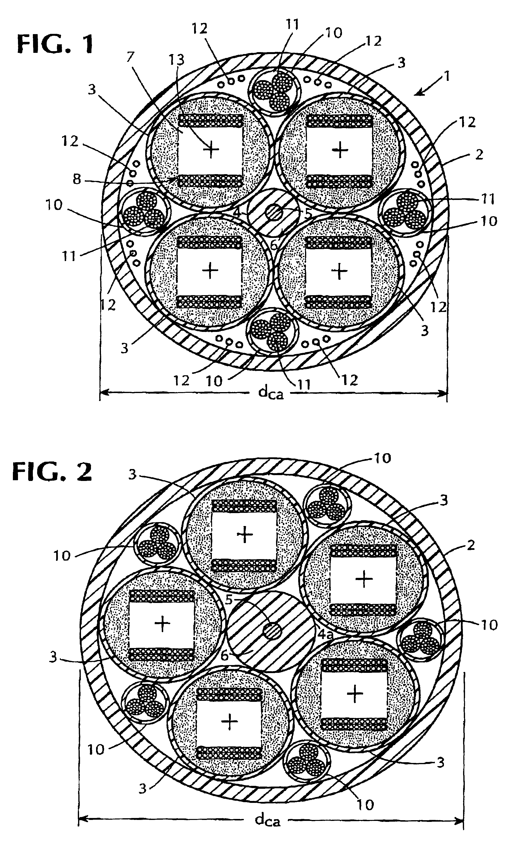
In the cable of the invention, optical fiber ribbons of the conventional size, buffer tubes of conventional wall thickness and ratio of bore size to ribbon stack size and a conventional jacket are used, but four buffer tubes, rather than the conventional six buffer tubes, are used for a cable compatible with a 1.5 inch duct. For a cable compatible with a 2 inch duct, the cable of the invention can have four or five buffer tubes, and it is possible to increase the total number of optical fibers by using ribbon stacks with ribbons containing different numbers of optical fibers. The buffer tubes are disposed, each in contact with adjacent tubes, around and in contact with a central strength member structure which, as a result of using four or five buffer tubes, can be reduced in diameter as compared to cables with a greater number of tubes, to provide increased space available for other elements, such as, optical fiber ribbons.
As compared to other cables compatible with a two inch duct, the cable of the invention has a lower fill factor and / or a higher fiber count.

Problems solved by technology

Ideally, such access should disturb the minimum number of fibers not being accessed.
On the other hand, the flexibility of a loose tube cable decreases with the number of buffer tubes included in the cable, and therefore, the prior art practice of increasing the number of buffer tubes, e.g., to six tubes, to increase the optical fiber count not only increases the cable diameter and hence, the fill factor, but also reduces the cable flexibility.
Also, an increase in the number of buffer tubes increases the cost of manufacturing a cable.
The increase in fiber count of such a loose tube cable with optical fiber ribbons cannot be obtained by merely increasing the number of ribbons in a loose tube cable having the required size.
Thus, the optical fiber ribbons used to meet the present practices have a standard size and have their own requirements such that the fibers and the ribbons cannot be significantly reduced in size.

Method used


Image

  • High fiber count optical fiber cable with buffer tubes around central strength member
  • High fiber count optical fiber cable with buffer tubes around central strength member
  • High fiber count optical fiber cable with buffer tubes around central strength member

Examples


Embodiment Construction

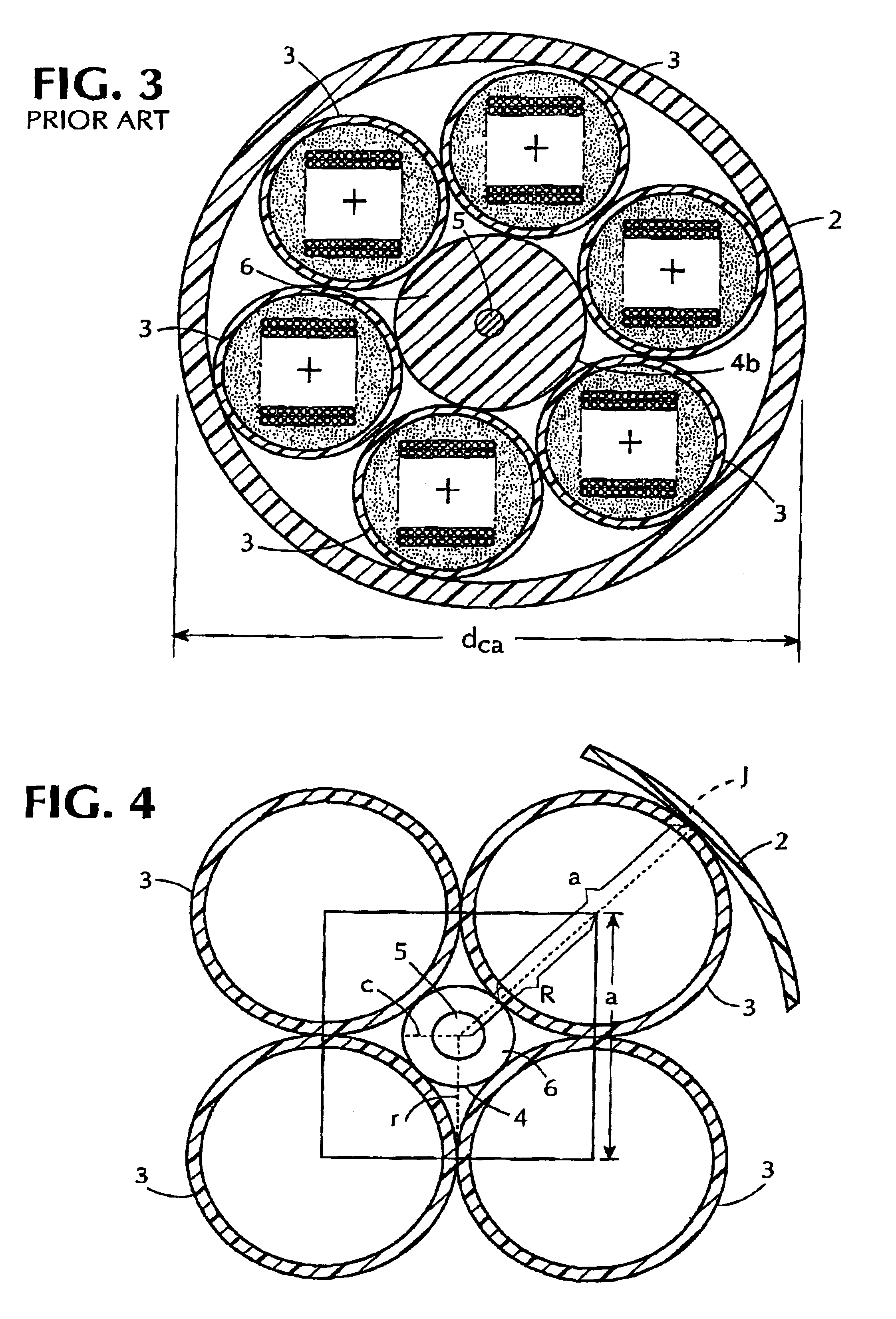
A four buffer tube embodiment of the optical fiber cable of the invention is illustrated in FIG. 1, but before describing the cable 1 illustrated in FIG. 1, the difficulties in designing an optical fiber cable which can be fed in a 1.5 inch (38.1 mm) duct and which has substantially in excess of 1000 optical fibers must be considered. Reference to the schematic diagram of FIGS. 2-4 will be made for this purpose.

The space within the cable jacket 2 is most efficiently used for containing optical fibers when the buffer tubes 3 contact each other and extend from the outer surface of the central strength member to the inner surface of the jacket 2. Also, contact of the buffer tubes 3 with the outer surface of the central strength member 4, 4a, 4b around which the buffer tubes 3 are wound simplifies the manufacturing process. The core 5 of the strength member, which is preferably a steel wire or a bare e-glass and which supplies most of the resistance to tension and compression forces on ...


PUM


Abstract

Optical fiber cable with a central strength member structure and with four or five buffer tubes each loosely receiving optical fiber ribbons in a stack and is disposed around and contacting the strength member. The optical fiber count is in excess of 1000 and the fill factor is not greater than 85% in a two inch duct. Each buffer tube contacts adjacent buffer tubes, and the buffer tubes are encircled by a jacket. Optionally, spaces bounded by pairs of buffer tubes and the jacket have optical fibers therein and can also include flexible longitudinal strength members and/or water blocking filaments. Preferably, the strength member structure and/or the buffer tubes are encircled by a water blocking tape. The optical fiber ribbons in the stacks can include different numbers of fibers, and hence, can have different width.

Description

FIELD OF THE INVENTIONThe invention relates to optical fiber communication cables comprising buffer tubes which loosely receive optical fiber ribbons and which are disposed around a central strength member and particularly, to such a cable with a high optical fiber count and with a relatively small diameter.BACKGROUND OF THE INVENTIONThere are various types of optical fiber cables including what are sometimes called a single tube cable, a loose tube cable and a slotted core cable. In a single tube cable a tube of plastic or other material has its axis coaxial with the cable axis and loosely receives individual optical fibers or optical fibers in side-by-side relation in one or more ribbons. Usually externally of the tube, such as in a cable jacket which encircles the tube, there are strength members used to resist tensile and compressive forces applied to the cable.In a so-called loose tube cable, there is a central strength member for resisting such forces and a plurality of plasti...

Claims


Application Information

Patent Timeline
Patent Type & Authority Patents(United States)
IPC IPC(8): G02B6/44
CPCG02B6/4403G02B6/4411G02B6/4434
Inventor JOHNSON, J. PETERAULL, ROBERT S.PETRYSZAK, MIKE
Owner PRYSMIAN COMM CABLES & SYST USA LLC
Why Eureka
Try Eureka