Reducing fill and improving quality of interlaced displays using multi-sampling

Inactive Publication Date: 2005-03-22
MICROSOFT TECH LICENSING LLC
View PDF19 Cites 5 Cited by
  • Summary
  • Abstract
  • Description
  • Claims
  • Application Information

AI Technical Summary

Benefits of technology

The present invention provides a system, method and computer program product for reducing fill and improving quality of interlaced displays using over-sampling. In an embodiment of the invention, a frame buffer for an interlaced display is filled. Initially, a first multi-sample of the first line of the first field is calculated. The bottom sub-pixels of the first multi-sample are the top sub-pixels of a multi-sample of the first line of the second field, i.e., the bottom sub-pixels of the first multi-sample are over-sampled. The first multi-sample is written into the frame buffer. Then, a second multi-sample of the second line of the first field is calculated. The top sub-pixels of the second multi-sample are the bottom sub-pixels of a multi-sample of the first line of the second field, i.e., the top sub-pixels of the second multi-sample are over-sampled. Also, the bottom sub-pixels of the second multi-sample are the top sub-pixels of the second line of the second field, i.e., the bottom sub-pixels of the second multi-sample are over-sampled. The second multi-sample is written into the frame buffer. A multi-sample for each subsequent line of the first field is calculated in this manner and written into the frame buffer. Then, a last multi-sample consisting of the bottom sub-pixels of a full multi-sample of the last line of the second field is calculated. The last multi-sample is also written into the frame buffer.
An advantage of the present invention is the decrease in the frame buffer size requirement. Whereas a typical frame buffer fill method requires two times N multi-sampled lines (where N is the number of multi-sampled lines in a field) of frame buffer space, the present invention requires only N+1 multi-sampled lines of frame buffer space. This allows for more efficient use of memory and reduces read / write operations.
Another advantage of the present invention is the increase in image quality. The present invention reduces vertical high frequency data which causes flickering and other unwanted visual effects. Increased image quality allows for easier viewing by users and the more accurate display of data.
Yet another advantage of the present invention is a reduction in fill processing. Because there is less information being written into the frame buffer, there is less fill processing required. This allows for a more efficient use of processing resources.
Yet another advantage of the present invention is a reduction in fill processing due to calculation of resultant lines upon fetch and not upon fill (as described above). This allows for a more efficient use of processing resources. Furthermore, the frame buffer is filled with one field at a time at field rate. That is, the frame buffer is refreshed with a new field at field rate, as opposed to refreshing the frame buffer with a new frame at frame rate. This allows for the fill processing to occur at the same rate as the display which results in better synchronization of the system.

Problems solved by technology

Interlaced scanning, however, does not come without drawbacks.
Because interlaced scanning displays only one half of the lines of an image at a time, images with high-frequency vertical information tend to flicker or have other visual aberrations, reducing visual accuracy.
Thus, at any given time, the frame buffer contains twice as many lines than are needed for each of the two passes (once for even-numbered lines and once for odd-numbered lines), which is an inefficient use of fill resources.

Method used


Image

  • Reducing fill and improving quality of interlaced displays using multi-sampling
  • Reducing fill and improving quality of interlaced displays using multi-sampling
  • Reducing fill and improving quality of interlaced displays using multi-sampling

Examples


Embodiment Construction

Discussion

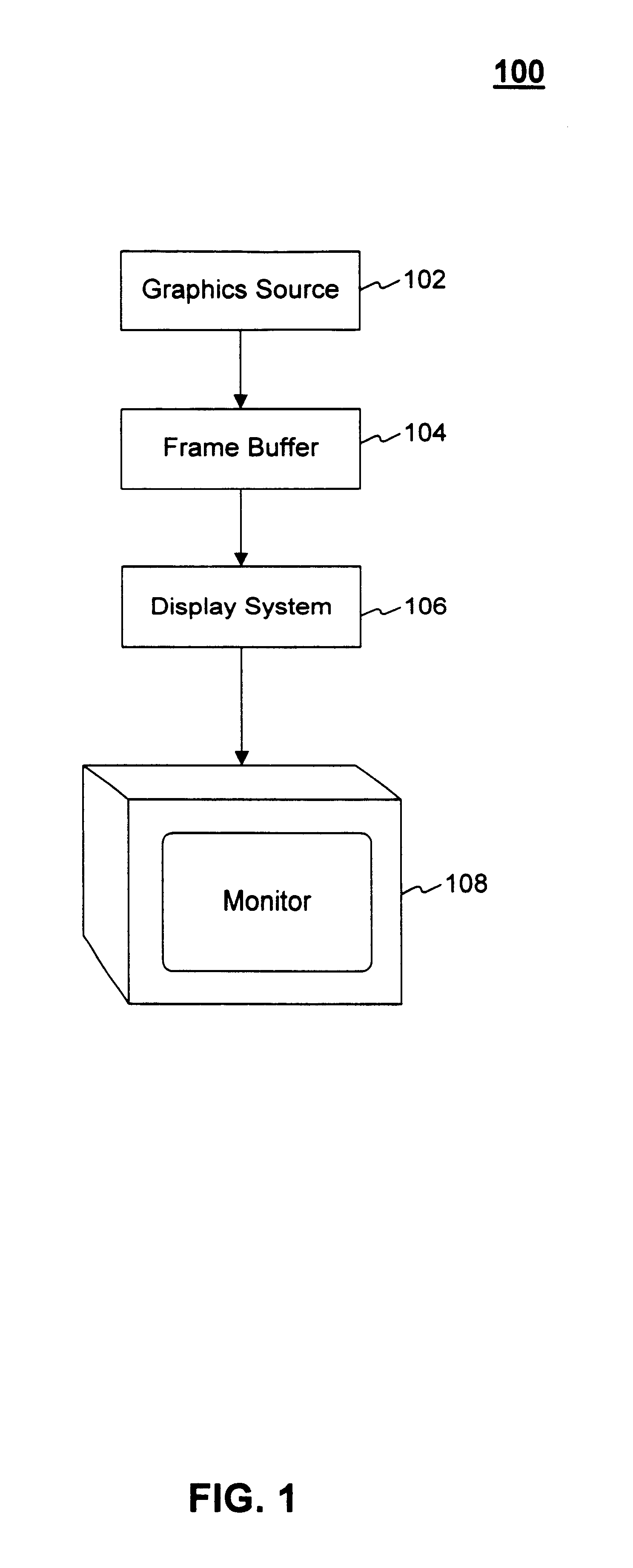
The present invention is directed towards a system method and computer program product for reducing fill and improving quality of interlaced displays using multi-samples. The present invention is described in terms of a software environment. Description in these terms is provided for convenience only. It is not intended that the present invention be limited to application in this example environment. In fact, after reading the following description, it will become apparent to the person skilled in the relevant art how to implement the invention in alternative environments known now or developed in the future.

Terminology

To more clearly delineate the present invention, an effort is made throughout the specification to adhere to the following term definitions as consistently as possible.

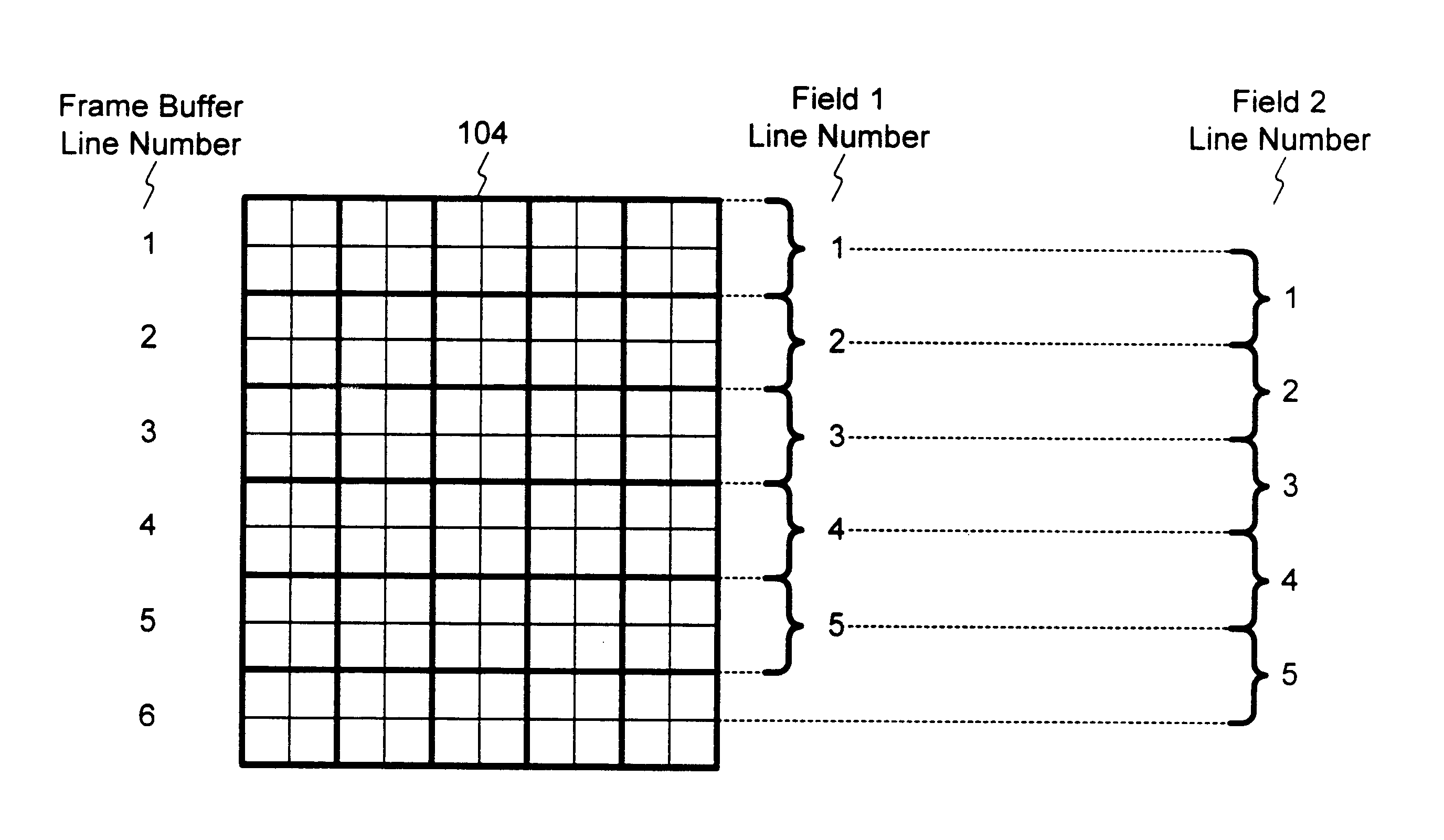
The term “frame” is used to refer to a single image in a sequence of images. A video clip consists of multiple frames.

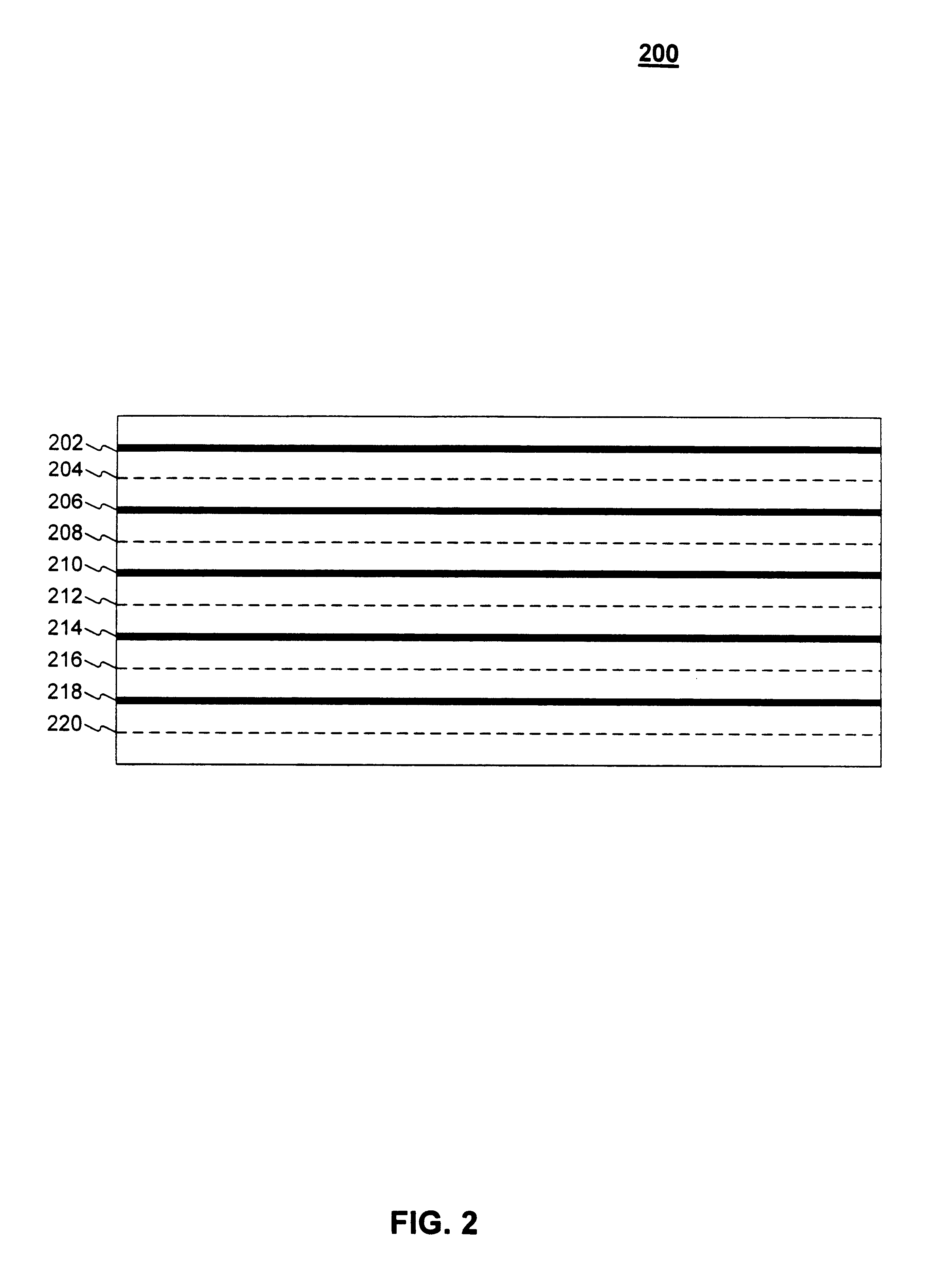
The terms “interlacing” and “interlaced scanning” are used to refer to a v...


PUM


Abstract

The present invention provides a system, method and computer program product for reducing fill and improving quality of interlaced displays using multi-sampling. In an embodiment of the invention, a frame buffer for a interlaced display is filled. Initially, a first multi-sample of the first line of the first field is calculated. The bottom sub-pixels of the first multi-sample are the top sub-pixels of a multi-sample of the first line of the second field. The first multi-sample is written into the frame buffer. Then, a second multi-sample of the second line of the first field is calculated. The top sub-pixels of the second multi-sample are the bottom sub-pixels of a multi-sample of the first line of the second field. Also, the bottom sub-pixels of the second multi-sample are the top sub-pixels of the second line of the second field. The second multi-sample is written into the frame buffer. A multi-sample for each subsequent line of the first field is calculated in this manner and written into the frame buffer. Then, a last multi-sample consisting of the bottom sub-pixels of a full multi-sample of the last line of the second field is calculated. The last multi-sample is also written into the frame buffer.

Description

BACKGROUND OF THE INVENTION1. Field of the InventionThe present invention relates generally to the field of computer graphics. More specifically, the present invention relates to the field of computer graphics for interlaced displays.2. Related ArtThe two most commonly used means of refreshing (i.e., displaying images on) a Cathode Ray Tube (CRT) display are progressive scanning and interlaced scanning. Progressive scanning, used by most computer displays, starts at the top of the image, scans the first line of the image and then scans each subsequent line of the image. Interlaced scanning starts at the top of the image, scans the first even-numbered line of the image, scans each subsequent even-numbered line of the image, returns to the top of the image and then proceeds to scan the odd-numbered lines of the image. Interlaced scanning reduces bandwidth by requiring less data during each of the two passes on the CRT. Interlaced scanning, however, does not come without drawbacks.Beca...

Claims


Application Information

Patent Timeline
IPC IPC(8): G09G5/02G09G5/39G09G5/00G09G5/36G09G1/06H04N11/06H04N11/20G09G5/393
CPCG09G5/39G09G2310/0224G09G5/393
Inventor EITZMANN, GREGORY M.
Owner MICROSOFT TECH LICENSING LLC
Why Eureka
Try Eureka