
Magnetic recording medium and magnetic recording/reproducing device

a recording medium and magnetic technology, applied in the field of magnetic recording medium and magnetic recording/reproducing device, can solve problems such as corrosion on the side surfaces of recording elements, and achieve the effects of less liable for damage, favorable recording/reproducing characteristics, and high reliability

Inactive Publication Date: 2006-08-24
TDK CORPARATION
View PDF3 Cites 7 Cited by
  • Summary
  • Abstract
  • Description
  • Claims
  • Application Information

AI Technical Summary

Benefits of technology

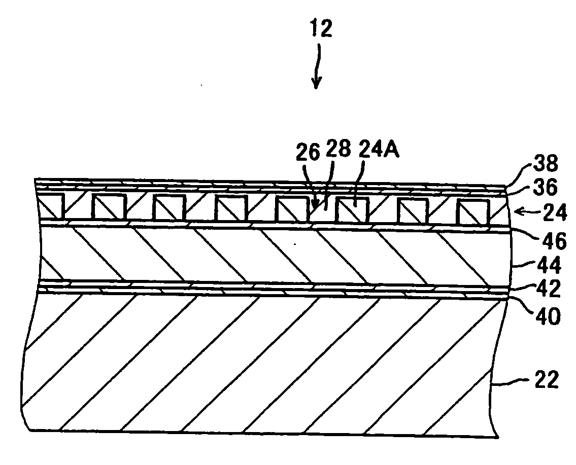
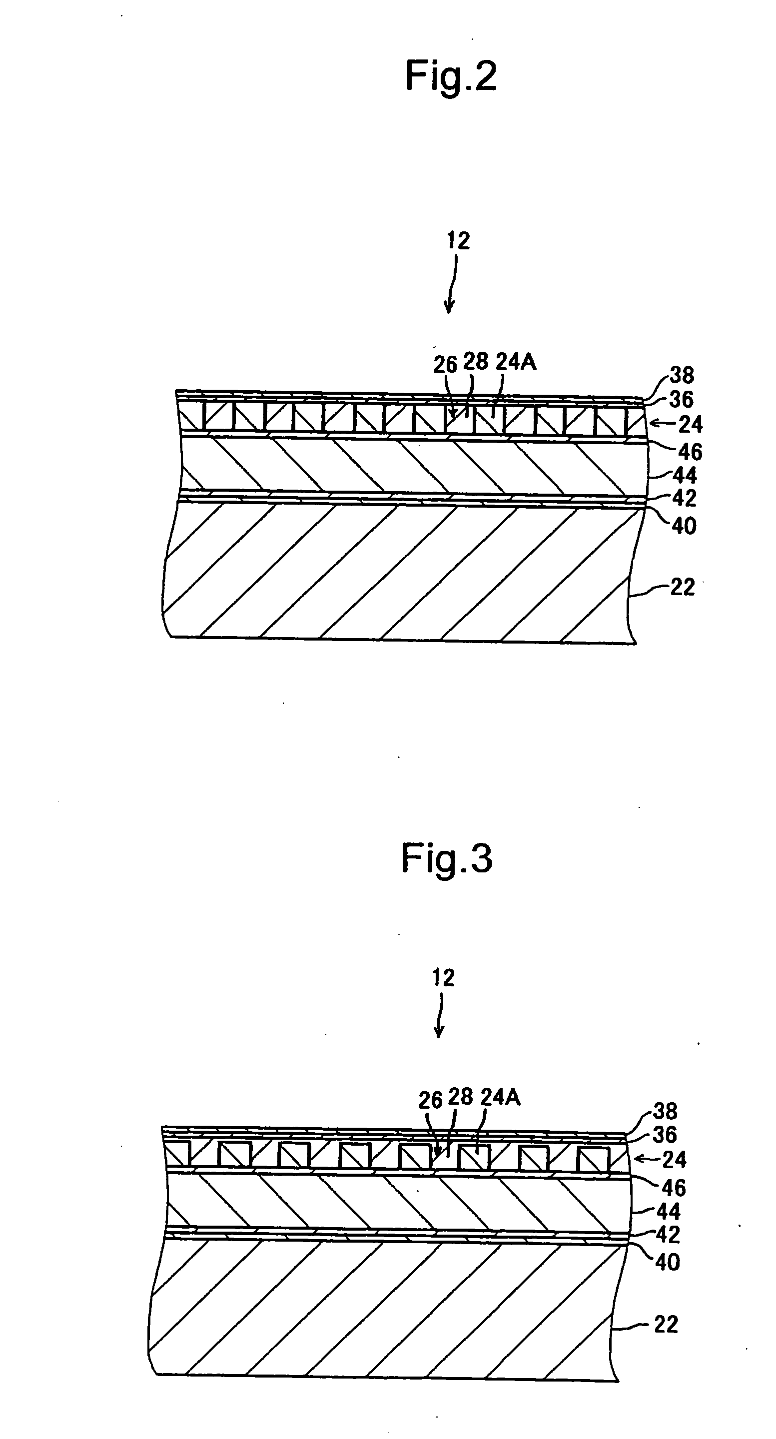
[0011] In view of the foregoing problems, various exemplary embodiments of the invention provide a highly reliable magnetic recording medium including a recording layer having recording elements formed as convex portions and a filling material filled within the concave portions between the recording elements and a magnetic recording / reproducing device including such a magnetic recording medium. The surface of the magnetic recording medium is less liable to damages when a magnetic head contacts the surface, and this medium can ensure favorable recording / reproducing characteristics.
[0013] In course of conceiving the invention, the inventors diligently investigated the cause of the degradation of the recording / reproducing characteristics of a magnetic recording medium using SiO2 as a filling material. Then, they found that corrosion on the side surfaces of recording elements was one of the reasons for the degradation. The side surfaces of recording elements are directly affected by processing such as dry-etching to form the recording layer in a concavo-convex pattern, and therefore the surfaces may be more easily corroded than the other parts.
[0014] Then, the inventors tried various materials as a filling material and found that the use of a filling material substantially composed of Si (silicon) and O (oxygen) in which the ratio of the number of O atoms to the number of Si atoms was less than 2 allowed the side surfaces of recording elements to be more resistant to corrosion. More specifically, when the ratio of the number of O atoms to the number of Si atoms is smaller than that in SiO2 that is a compound generally believed to be a chemically stable, the side surfaces of the recording elements can be more resistant to corrosion. The reason why this effect is brought about is not necessarily clear, but it is considered that when the ratio of the number of O atoms to the number of Si atoms in the material is smaller than SiO2, the filling material is more closely packed, so that oxygen or moisture reaching the side surfaces of the recording elements through the filling material is reduced, and the side surfaces of the recording elements are less corroded.
[0015] Note that when the ratio of the number of O atoms to the number of Si atoms is less than 1.9, the effect of corrosion resistance on the side surfaces of the recording elements can be further increased.
[0016] Meanwhile, the inventors found that when the ratio of the number of O atoms to the number of Si atoms was less than 1.5, the surface of the magnetic recording medium was more liable to damages. The reason for the phenomenon is not necessarily clear either, but it is considered that when the ratio of the number of O atoms to the number of Si atoms was excessively small, the rigidity and hardness of the filling material were lowered, and the protective layer borne on the filling material was excessively deformed and damaged as it came in contact with the magnetic head. Meanwhile, when the ratio of the number of O atoms to the number of Si atoms is equal to or more than 1.5, damages inflicted on the surface of the magnetic recording medium for contact with the magnetic head can be suppressed.
[0023] Various exemplary embodiments of the invention achieve a magnetic recording medium that includes a recording layer having recording elements formed as convex portions and a filling material filled within the concave portions between the recording elements and a magnetic recording / reproducing device including such a medium. The medium is highly reliable and has a surface less liable to damages when a magnetic head comes in contact with it, so that good recording / reproducing characteristics are ensured.

Problems solved by technology

Then, they found that corrosion on the side surfaces of recording elements was one of the reasons for the degradation.

Method used


Image

  • Magnetic recording medium and magnetic recording/reproducing device
  • Magnetic recording medium and magnetic recording/reproducing device
  • Magnetic recording medium and magnetic recording/reproducing device

Examples


experimental example 1

[0053] Twenty samples of each of seven kinds having the structure the same as that of the magnetic recording medium 12 according to the first exemplary embodiment and 20 samples of one kind in which the ratio of the number of O atoms to the number of Si atoms in a filling material 28 was equal to or more than 2.0 were manufactured. Among these eight kinds of samples, the ratios of the number of O atoms to the number of Si atoms are different in their filling materials 28 (see Table 1) and the other structures are the same. Note that in Table 1, the ratio of the number of O atoms to the number of Si atoms in the filling material 28 in each kind of samples is given in increments of 0.1, and this is in consideration of the precision of measurement.

[0054] The substrate 22 had a diameter of approximately 65 mm and is made of glass. The recording layer 24 had a thickness of approximately 20 nm and is made of a CoCrPt alloy. The protective layer 36 had a thickness of approximately 4 nm an...

experimental example 2

[0064] As opposed to Experimental Example 1, 20 samples of each of eight kinds were manufactured. In each of the samples, a filling material 28 was deposited to have a thickness of approximately 20 nm on a continuous recording layer (yet to be processed) having a uniform thickness of 20 nm. Among these eight kinds of samples, the ratios of the number of O atoms to the number of Si atoms in their filling materials 28 are different from each other similarly to Experimental Example 1 described above (see Table 1). Note that in order to determine how effectively the filling material 28 serves to resist corrosion, the protective layer 36 and the lubricating layer 38 were not formed on the filling material 28. The other structures were the same as those of the samples in Experimental Example 1.

[0065] These eight kinds of samples were left to stand for approximately 48 hours in a high temperature and high humidity environment (at 80° C. with a humidity of 85%), and then their surfaces wer...


PUM

PropertyMeasurementUnit
thicknessaaaaaaaaaa
thicknessaaaaaaaaaa
thicknessaaaaaaaaaa

Abstract

A magnetic recording medium is provided that includes a recording layer having recording elements formed as convex portions and a filling material filled within the concave portions between the recording elements. The medium is highly reliable and has a surface less liable to damages when a magnetic head contacts the surface, so that good recording / reproducing characteristics are ensured. The magnetic recording medium includes a recording layer formed in a predetermined concavo-convex pattern over a substrate and having recording elements formed as convex portions in the concavo-convex pattern and a filling material filled within the concave portions between the recording elements. The filling material is substantially composed of Si and O, and the ratio of the number of O atoms to the number of Si atoms is equal to or more than 1.5 and less than 2.

Description

BACKGROUND OF THE INVENTION [0001] 1. Field of the Invention [0002] The present invention relates to a magnetic recording medium having recording elements formed as convex portions and a filling material filled within the concave portions between the recording elements and a magnetic recording / reproducing device including the medium. [0003] 2. Description of the Related Art [0004] The areal densities of conventional magnetic recording media such as a hard disk have come to be greatly increased with improvements such as miniaturization of magnetic grains forming the recording layers, modification of materials, or highly precise processing of the head. Even more improvements in the areal density are expected in the future. However, the limit of head processing, erroneous recording of information in a track adjacent to a target track caused by the broadening of a magnetic field and cross talk have been encountered, and improvements by the conventional techniques have reached the limit....

Claims


Application Information

Patent Timeline
Patent Type & Authority Applications(United States)
IPC IPC(8): G11B5/64
CPCG11B5/855
Inventor OKAWA, SHUICHITAKAI, MITSURUSHIMAKAWA, KAZUYA
Owner TDK CORPARATION
Learn More