
Airfoil refurbishment method

Inactive Publication Date: 2007-02-01
LAGRAFF JOHN ROBERT +5
View PDF15 Cites 19 Cited by
  • Summary
  • Abstract
  • Description
  • Claims
  • Application Information

AI Technical Summary

Benefits of technology

[0017] Accordingly, one aspect of the present invention is to provide an airfoil refurbishment system that includes an environmentally safe stripper system. The environmentally safe stripper system is capable of partially removing an aluminide coating from an airfoil.
[0019] Still another aspect of the present invention is to provide an airfoil refurbishment system that includes an environmentally safe stripper system and an aluminiding system. The environmentally safe stripper system includes a transportable environmentally safe compound that is capable of partially removing an aluminide coating from an airfoil. The aluminiding system is capable of restoring the aluminide coating to the airfoil.

Problems solved by technology

However, materials from which an airfoil is made may limit the operating temperature.
In time, however, a coating degrades.
There are several disadvantages with current refurbishment.
One major disadvantage is that no integrated system exists for refurbishment.
As a general rule, there is a dearth of equipment at the turbine overhaul site for performing any of the number of steps of airfoil refurbishment, let alone an integrated system for all of the steps of refurbishment.
As a turbine often is located in a first country, the first remote location is in a second country, and the second remote location is in a third country, the time for transporting airfoils can become frustrated by the time needed to clear customs of both the turbine location country and the remote location countries.
Another disadvantage of current refurbishment techniques for airfoils is the complete removal of the coating (i.e., the thermally grown oxide layer, alumide layer and diffusion layer).
Additionally, current refurbishment systems include environmentally hazardous operations, particularly, the coating removal operation.
The removal of the diffusion layer can thus, substantially decrease the life of an airfoil.

Method used


Image

  • Airfoil refurbishment method
  • Airfoil refurbishment method
  • Airfoil refurbishment method

Examples


Embodiment Construction

[0046] In the following description, like reference characters designate like or corresponding parts throughout the several views. Also in the following description, it is to be understood that such terms as “forward,”“rearward,”“left,”“right,”“upwardly,”“downwardly,” and the like are words of convenience and are not to be construed as limiting terms.

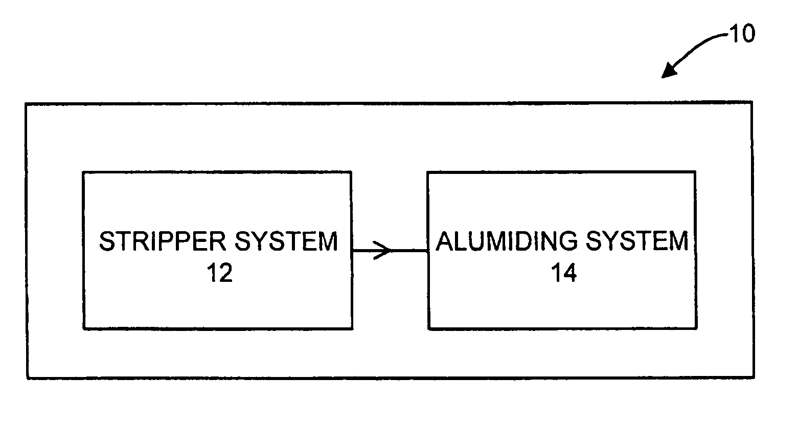
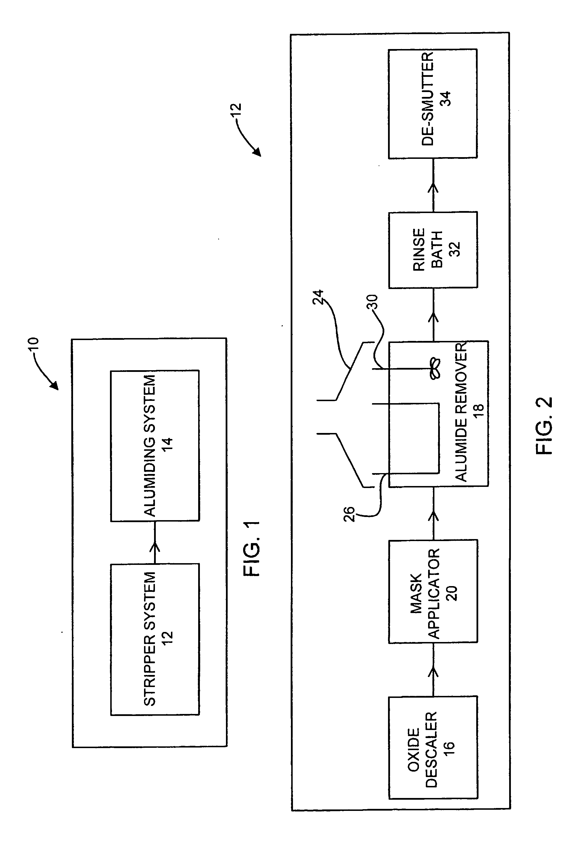
[0047] Referring now to the drawings in general and FIG. 1 in particular, it will be understood that the illustrations are for the purpose of describing a preferred embodiment of the invention and are not intended to limit the invention thereto. As best seen in FIG. 1, an airfoil refurbishment system, generally designated 10, is shown constructed according to the present invention. The airfoil refurbishment system 10 includes two major sub-assemblies, a stripper system 12 and an aluminiding system 14. As such, an airfoil refurbishment system 10 may be contained within a single building or a single facility.

[0048] One advantage of such...


PUM

PropertyMeasurementUnit
Areaaaaaaaaaaa

Abstract

An airfoil refurbishment system is disclosed. The airfoil refurbishment system includes an environmentally safe stripper system and an aluminiding system. The environmentally safe stripper system includes a transportable environmentally safe compound that is capable of partially removing an aluminide coating from an airfoil. The aluminiding system is capable of restoring the aluminide coating to the airfoil.

Description

BACKGROUND OF INVENTION [0001] The present invention generally relates to an airfoil refurbishment system and, more particularly, to a system including an environmentally safe stripper system that is capable of partially removing an aluminide coating from an airfoil. [0002] Airfoils are used in aircraft engine turbines and power generation turbines to translate combustion into rotational motion. In an aircraft engine turbine, the rotational motion is used to spin fans in the compressor to sustain rotation and fans that create thrust, which in conjunction with wings, lifts an aircraft for flight. In a power generation turbine, that rotational motion also is used to spin fans in the compressor to sustain rotation and, rather than fans, perform mechanical work such as the rotation of a generator to produce electricity. For either of these turbines, increasing the operating temperature of the turbine section can increase operating efficiency. However, materials from which an airfoil is ...

Claims


Application Information

Patent Timeline
IPC IPC(8): C23F1/00C23C16/00
CPCC23C10/02C23C10/04C23F1/02C23F1/16F05D2230/80F01D5/005G01N2800/52Y02T50/67C23F1/44Y02T50/60
Inventor LAGRAFF, JOHN ROBERTRUUD, JAMES ANTHONYPARK, DONG-SILMACDONALD, LEO SPITZBOTTOMS, JOHN JOSEPHKOAKOWSKI, CLAUDINO
Owner LAGRAFF JOHN ROBERT
Learn More