Coating and coating method for gas turbine engine component

a gas turbine engine and coating technology, applied in the direction of liquid fuel engine components, solid-state diffusion coatings, electrodialysis, etc., can solve the problems of ineffective masking in these processes and inability to apply in high-temperature processes

Inactive Publication Date: 2016-01-14
HOWMET CORPORATION
View PDF10 Cites 23 Cited by
  • Summary
  • Abstract
  • Description
  • Claims
  • Application Information

AI Technical Summary

Benefits of technology

[0006]The present invention provides in an embodiment a method of forming a protective coating on a gas turbine component wherein the duplex coating includes an aluminum-bearing coating applied at one region of the gas turbine component where relatively higher temperatures are encountered in service and a chromium-bearing coating applied at another region of the turbine blade or other component where relatively lower temperatures and hot corrosion are encountered in service, thereby providing coating functionality for the different temperatures and oxidation / corrosion environments to be encountered by the gas turbine component.
[0008]In the event the substrate is a gas turbine component, the method is practiced by first applying a mask on a root region of the component, then applying an aluminum-bearing coating, such as a diffusion aluminide coating, on an airfoil region, de-masking the root portion, and then masking the already-coated airfoil region. Then, the method involves depositing a metallic coating comprising chromium on at least a portion of a relatively lower temperature root region that will be subject to hot corrosion, de-masking the airfoil region followed by diffusing the chromium into the alloy at the coated portion of the root region to form a chromium-enriched diffused surface coating on the portion of the root region. The aluminum-bearing coating optionally can be applied to cover the airfoil region and also an intermediate platform region and root shank region. An attachment portion, such as a fir tree portion, of the root region may be left uncoated to enhance fatigue life of the root region where it is connected to a turbine disk.

Problems solved by technology

Since pack and vapor phase chromizing require high temperature application above 1900 F and are difficult to apply to localized part areas of interest, these processes must be applied early in the part routing to the entire the part.
Masking has not been effective in these processes as a means for controlling the localized deposition of the chromium on certain areas of interest and, as a result, has not been applied in these high temperature processes.

Method used


Image

  • Coating and coating method for gas turbine engine component
  • Coating and coating method for gas turbine engine component
  • Coating and coating method for gas turbine engine component

Examples


example 1

[0043]Pursuant to an illustrative embodiment of the present invention, the following processing steps are employed:

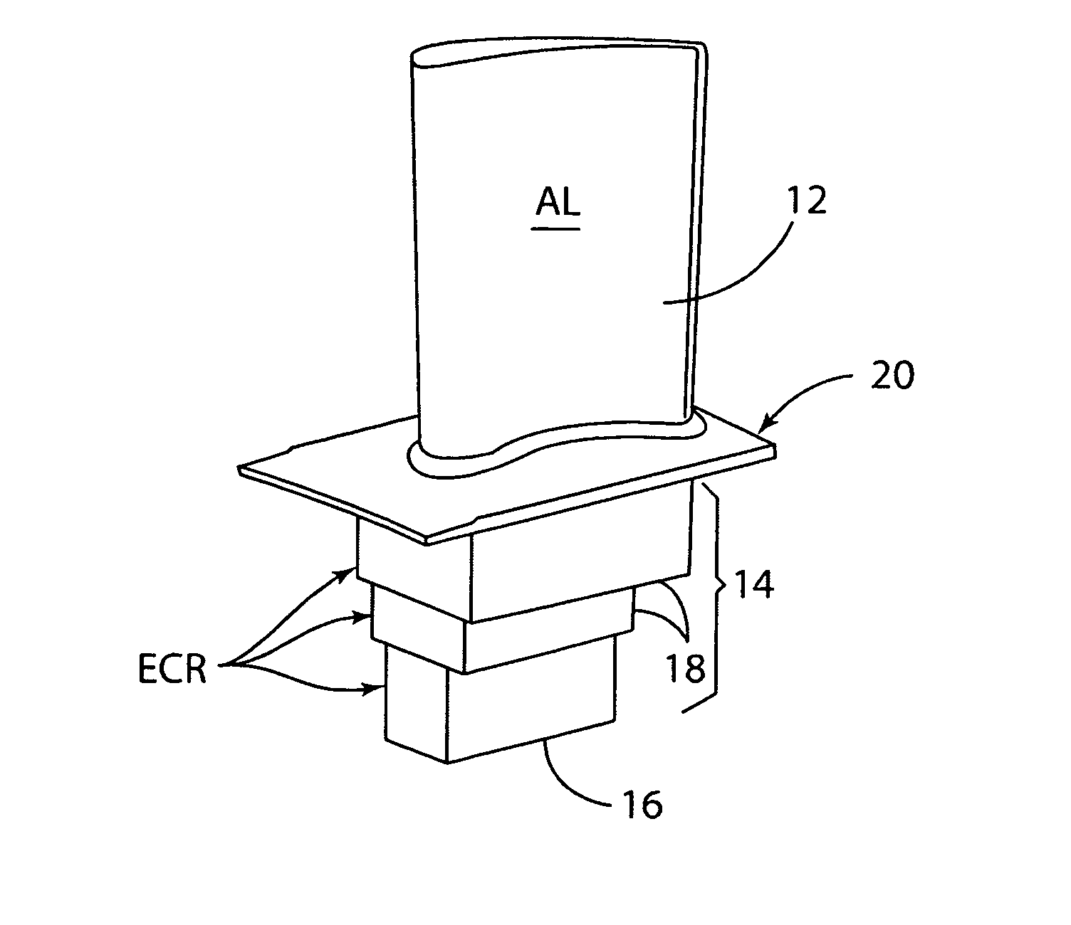
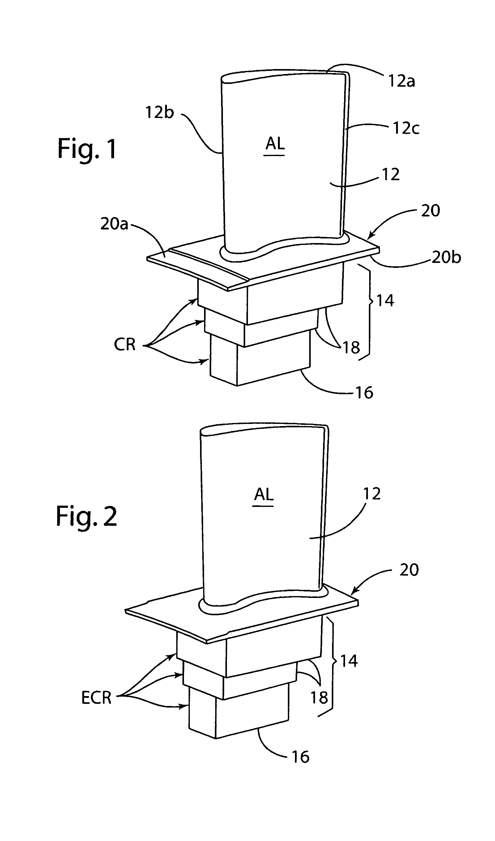
[0044]1. If a platinum-modified diffusion aluminide coating is to be formed on the gas path surfaces 12, 20a, then these surfaces are optionally electroplated with a layer of Pt pursuant to U.S. Pat. No. 5,788,832 which is already incorporated herein by reference. If a simple diffusion aluminde coating is to be formed, then this step is omitted.

[0045]2. Masking the second region of the turbine blade (i.e. root region 14 and platform surface 20b) with the M1 maskant powder mentioned above in a containment box. That is, the root region 14 and platform surface 20b are embedded in the maskant powder in the containment box.

[0046]3. Aluminize the first hotter region (i.e. airfoil 12 and platform surface 20a) to form a diffusion aluminide coating, such as a Pt-modified diffusion aluminide coating if step 1 is practiced, with the masking covering the second region.

[0047]4. Mask...

example 2

[0070]Pursuant to another illustrative embodiment of the present invention, the following processing steps are employed:

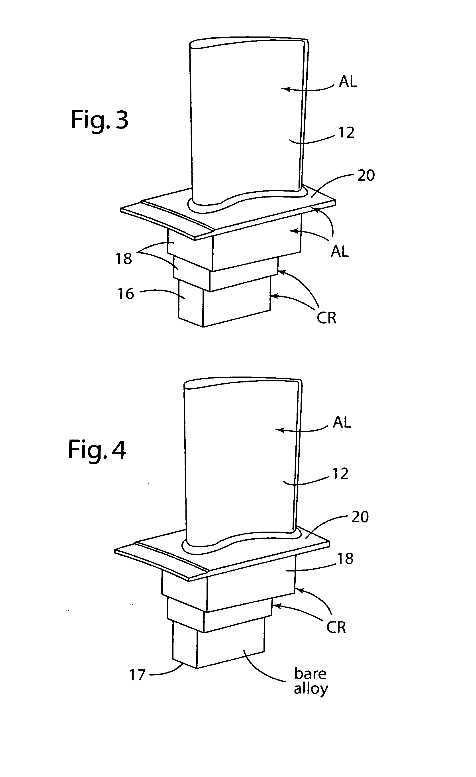
[0071]1. If a platinum-modified diffusion aluminide coating is to be formed on the gas path surfaces 12, 20a, then these surfaces are optionally electroplated with a layer of Pt pursuant to U.S. Pat. No. 5,788,832 which is already incorporated herein by reference. If a simple diffusion aluminide coating is to be formed, then this step is omitted.

[0072]2. Aluminize the first hotter region and the second region to form a diffusion aluminide coating, such as a Pt-modified diffusion aluminide coating. No masking covering the second region.

[0073]3. Removing the diffusion aluminide coating selectively from the second region by grit blasting, machining or other technique to expose the substrate alloy, while leaving the diffusion aluminide coating on the first region.

[0074]4. Masking the diffusion aluminide coating on the first region as described in Example 1.

[0075]5. Cr ...


PUM

PropertyMeasurementUnit
temperatureaaaaaaaaaa
thicknessaaaaaaaaaa
thicknessaaaaaaaaaa

Abstract

The present invention provides a protective coating for a gas turbine blade or other component wherein the duplex coating includes an aluminum-bearing coating, such as a diffusion aluminide, formed on a first, relatively higher temperature region of the blade / component and a later-applied chromium-bearing diffusion coating formed on an adjacent relatively lower temperature region of the blade / component subject to hot corrosion in service. The chromium-bearing coating is applied after the aluminum-bearing coating by masking that coating and depositing a metallic chromium coating on the adjacent region followed by diffusing the chromium into the blade / component alloy to form a chromium-enriched diffusion coating thereon.

Description

RELATED APPLICATION[0001]This application claims benefit and priority of U.S. provisional application Ser. No. 61 / 633,935 filed Feb. 21, 2012, the entire disclosure of which is incorporated herein by reference.FIELD OF THE INVENTION[0002]The present invention relates to a protective coating for a gas turbine blade or other component wherein the coating includes an aluminum-bearing coating applied at a relatively high temperature region of the component and a chromium-bearing coating applied at another relatively lower temperature region of the component depending on coating functionality needed.BACKGROUND OF THE INVENTION[0003]Current gas turbine designs are requiring that a variety of coatings be applied to different areas of the turbine part for different functional reasons. Examples of coating functionality include wear, oxidation, thermal barrier, and hot corrosion. Turbine designers choose an appropriate coating for a particular functionality in the gas turbine environment.[000...

Claims


Application Information

Patent Timeline
Patent Type & Authority Applications(United States)
IPC IPC(8): F01D5/28C25D5/02C25D5/12C25D13/02C25D13/16
CPCF01D5/288C25D5/022C25D13/16C25D13/02C25D5/12C23C10/02C23C10/58C25D13/12F01D5/3007F05D2300/132F05D2300/121C25D5/44C25D5/50F05D2230/31C25D3/04
Inventor MURPHY, KENNETH S.BASTA, WILLIAM C.
Owner HOWMET CORPORATION
Why Eureka
Try Eureka