Weather strip
a technology of weather strip and sleeve, which is applied in the direction of roofs, doors, transportation and packaging, etc., can solve the problems of difficult remounting, portion b>, and the insatisfactory demand for a light-weight vehicl
- Summary
- Abstract
- Description
- Claims
- Application Information
AI Technical Summary
Benefits of technology
Problems solved by technology
Method used
Image

Examples
first embodiment
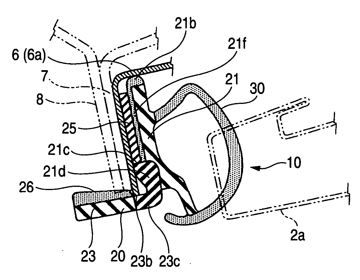
[0113] Next, based on FIG. 1, a cross sectional shape of the opening trim weather strip 10 according to the first embodiment of the invention will be described.
[0114] The opening trim weather strip 10 has a trim portion (a mounting base portion) 20 having a substantially L-shaped cross section which is to be mounted on the flange 7 and a hollow seal portion 30 which is formed integrally on the trim portion 20 so as to be brought into contact with a door frame projecting portion 2a of the door 2 so as to seal a gap between the door 2 and the vehicle body opening peripheral part 6.
[0115] The trim portion 20 is provided with an exterior side wall 21 and a bottom wall 23 and is bent integrally into an L-like shape. In order to flexibly follow a variation in thickness of the flange 7, the trim portion 20 is provided with the exterior side wall 21 and the bottom wall 23 and has no interior side wall which should otherwise be provided on an interior side thereof. However, a holding lip m...
second embodiment
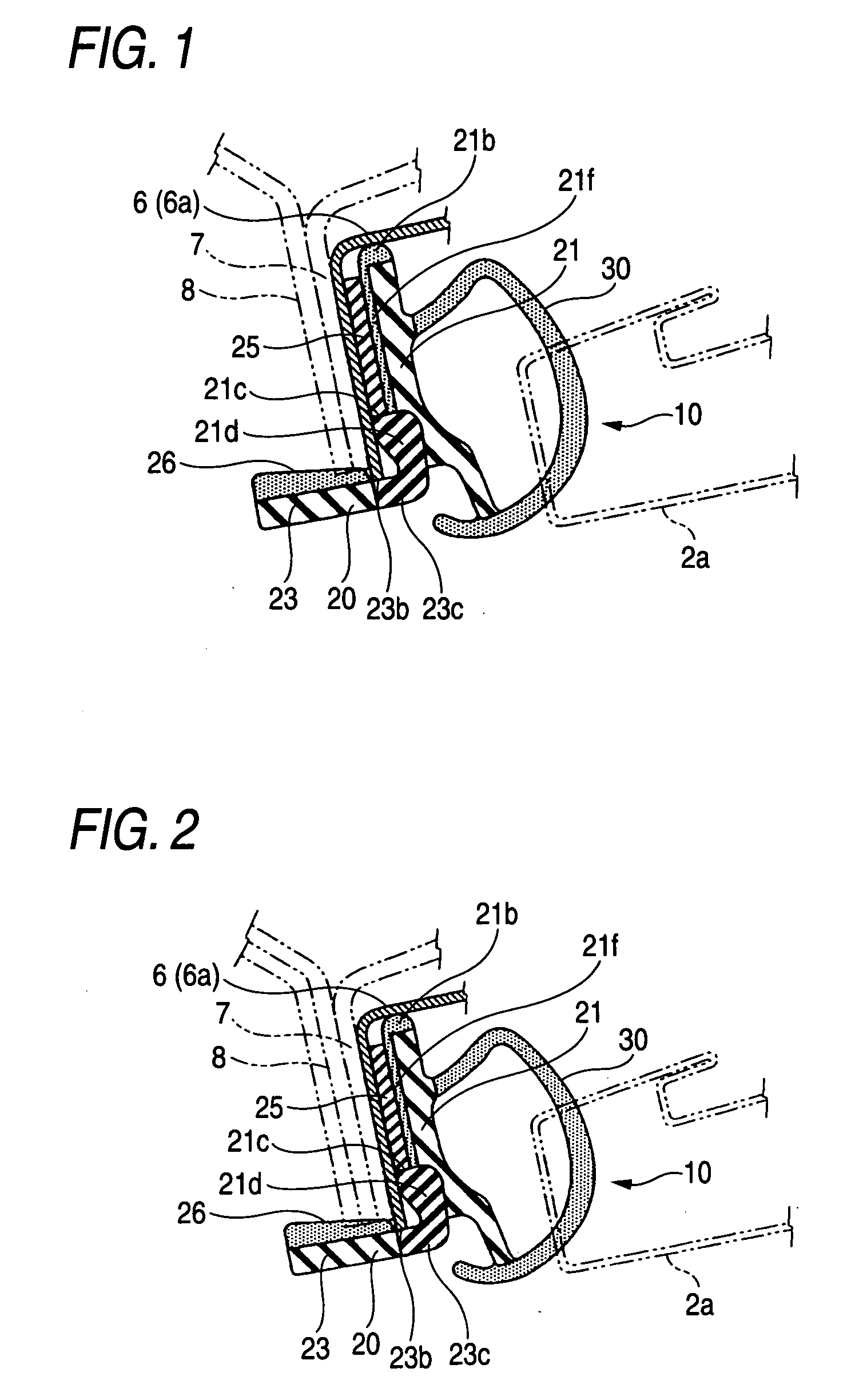
[0138] Next, a second embodiment of the invention will be described based on FIG. 2. The second embodiment differs from the first embodiment in that a bottom wall 23 is different from that of the first embodiment with the other constituent portions remaining the same as those of the first embodiment, and therefore, only the different portion will be described and the description of the same portions will be omitted.
[0139] A bottom wall 23 is formed into a substantially flat plate-like shape and is formed of a hard material as a whole including a bottom wall connecting portion 23c which is a continuous portion to an exterior side wall 21. Due to this, the bottom wall 23 can be formed of a hard member integrally from the bottom wall connecting portion 23c to a distal end of the bottom wall 23, whereby even in the event that a distal end of a flange 7 is brought into contact with the bottom wall 23 and a caulking sponge 26, the bottom wall 23 is made difficult to be deformed, thereby ...
third embodiment
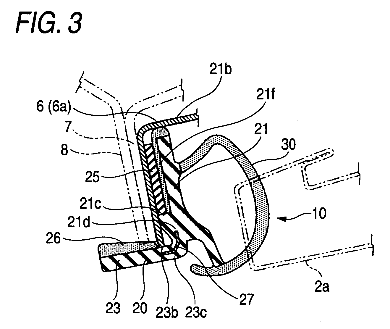
[0140] Next, a third embodiment of the invention will be described based on FIG. 3. The third embodiment differs from the first embodiment in that an insert member 27 is embedded in a bottom wall connecting portion 23c and an exterior side wall connecting portion 21d with the other constituent portions remaining the same as those of the first embodiment, and therefore, only the different portion will be described and the description of the same portions will be omitted.
[0141] As shown in FIG. 3, the insert member 27 is embedded in a bent continuous portion which stretches between an exterior side wall 21 and a bottom wall 23, that is, in the exterior side wall connecting portion 21d and the bottom wall connecting portion 23c so as to be bent at substantially right angles as seen in cross section to follow a bent angle.
[0142] Due to this, a sufficient rigidity can be given to a connecting portion between the exterior side wall connecting portion 21d and the bottom wall connecting p...
PUM
 Abstract
Description
Claims
Application Information
 - R&D
- Intellectual Property
- Life Sciences
- Materials
- Tech Scout
- Unparalleled Data Quality
- Higher Quality Content
- 60% Fewer Hallucinations
Browse by: Latest US Patents, China's latest patents, Technical Efficacy Thesaurus, Application Domain, Technology Topic, Popular Technical Reports.
© 2025 PatSnap. All rights reserved.Legal|Privacy policy|Modern Slavery Act Transparency Statement|Sitemap|About US| Contact US: help@patsnap.com