Methods and apparatus for cooling wind turbine generators

a wind turbine generator and cooling apparatus technology, applied in the direction of electric generator control, magnetic circuit shape/form/construction, magnetic circuit rotating parts, etc., can solve the problems of conventional systems that require maintenance and power to operate, conventional systems are typically complex and require additional components, and the core and coil generate a significant amount of hea

Inactive Publication Date: 2007-02-01
GENERAL ELECTRIC CO
View PDF5 Cites 104 Cited by
  • Summary
  • Abstract
  • Description
  • Claims
  • Application Information

AI Technical Summary

Problems solved by technology

However, when the electricity is generated in the core and coil, the core and coil generate a significant amount of heat.
These conventional systems are typically complex and require

Method used


Image

  • Methods and apparatus for cooling wind turbine generators
  • Methods and apparatus for cooling wind turbine generators
  • Methods and apparatus for cooling wind turbine generators

Examples


Embodiment Construction

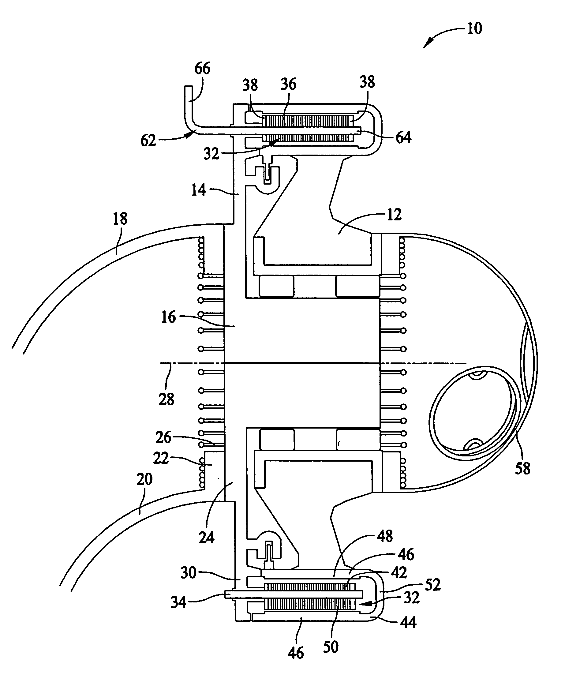
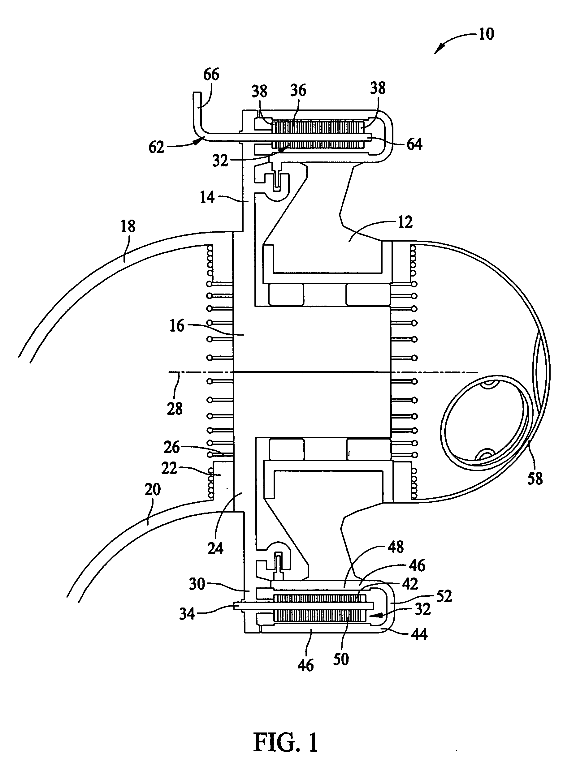
[0018]FIG. 1 is a schematic elevation illustration of an exemplary wind turbine generator 10 that includes a rotor 12 and a stator 14. Rotor 12 and stator 14 are separated by a bearing 16. In the exemplary embodiment, a base 18 couples to a tower (not shown). Base 18 includes a body 20 and a base flange 22. Stator 14 is configured to couple to base flange 22 through face to face engagement of base flange 22 and a complementary stator flange 24. In the exemplary embodiment, stator 14 is fastened to mating flange 22 through a plurality of bolts 26 spaced circumferentially about a longitudinal axis 28 of generator 10. In an alternative embodiment, stator 14 is fastened to base flange 22 using weldment and / or other fasteners. Stator 14 also includes a core mount rim 30 that extends axially from stator flange 24. In the exemplary embodiment, a stator core 32 is coupled to core mount rim 30 using bolts 34. In one embodiment, stator core 32 includes a plurality of punchings 36, e.g. lamina...


PUM


Abstract

A wind turbine generator includes a stator having a core and a plurality of stator windings circumferentially spaced about a generator longitudinal axis. A rotor is rotatable about the generator longitudinal axis, and the rotor includes a plurality of magnetic elements coupled to the rotor and cooperating with the stator windings. The magnetic elements are configured to generate a magnetic field and the stator windings are configured to interact with the magnetic field to generate a voltage in the stator windings. A heat pipe assembly thermally engaging one of the stator and the rotor to dissipate heat generated in the stator or rotor.

Description

BACKGROUND OF THE INVENTION [0001] This invention relates generally to wind turbine generators, and more particularly, to methods and apparatus for cooling wind turbine generators. [0002] Recently, wind turbines have received increased attention as an environmentally safe and relatively inexpensive alternative energy source. With this growing interest, considerable efforts have been made to develop wind turbines that are reliable and efficient. [0003] Generally, a wind turbine includes a plurality of blades coupled to a rotor through a hub. The rotor is mounted within a housing or nacelle, which is positioned on top of a tubular tower or base. Utility grade wind turbines (i.e., wind turbines designed to provide electrical power to a utility grid) can have large rotors (e.g., 30 or more meters in diameter). Blades on these rotors transform wind energy into a rotational torque or force that drives the rotor of one or more generators, rotationally coupled to the rotor. The rotor is sup...

Claims


Application Information

Patent Timeline
IPC IPC(8): F03D9/00H02K3/24H02K1/22
CPCF03D1/06F03D9/002F05B2220/7066F05B2220/7068F16C2360/31H02K9/20Y02E10/721Y02E10/725H02K7/1838F05B2260/20F03D9/25F03D80/60Y02E10/72H02K9/225
Inventor SALAMAH, SAMIR A.GADRE, ANIRUDDHA DATTATRAYAGARG, JIVTESHBAGEPALLI, BHARAT SAMPATHKUMARANJANSEN, PATRICK LEECARL, RALPH JAMES JR.
Owner GENERAL ELECTRIC CO
Why Eureka
Try Eureka