Temperature fuse element, temperature fuse and battery using the same
a technology of temperature fuse and temperature fuse, which is applied in the direction of battery, primary cell maintenance/service, cell components, etc., can solve the problems of increasing the tendency to speed up the temperature rise rate, affecting the natural environment, and affecting the operation of electrical devices, so as to achieve the effect of suppressing the harm to the natural environmen
- Summary
- Abstract
- Description
- Claims
- Application Information
AI Technical Summary
Benefits of technology
Problems solved by technology
Method used
Image
Examples
first embodiment
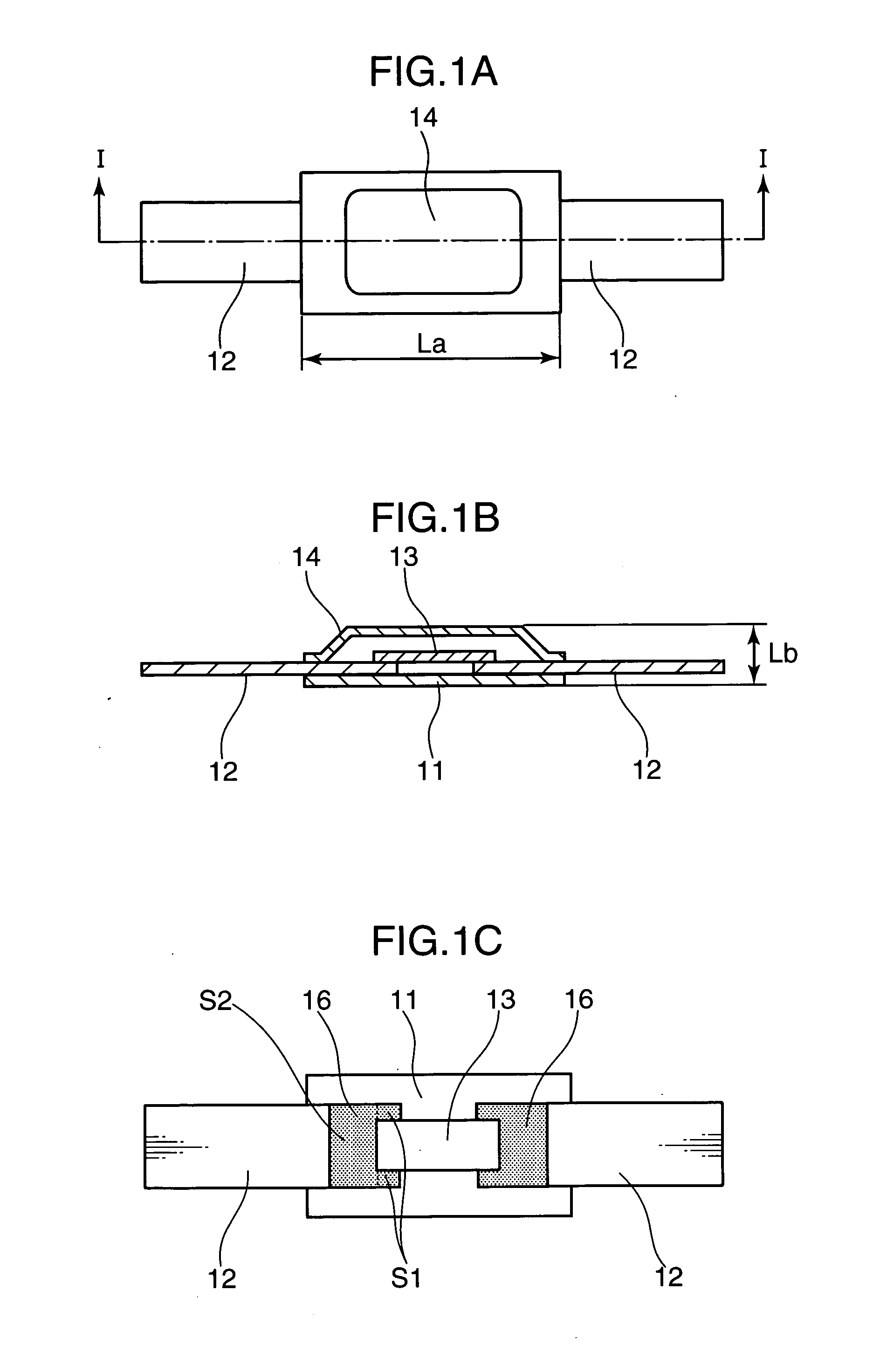
[0056]FIGS. 1A to 1C are views showing the construction of a thin-type thermal fuse according to a first embodiment of the invention, wherein FIG. 1A is a top view, FIG. 1B is a section along I-I of FIG. 1A, and FIG. 1C is a top view partly in section corresponding to FIG. 1A.
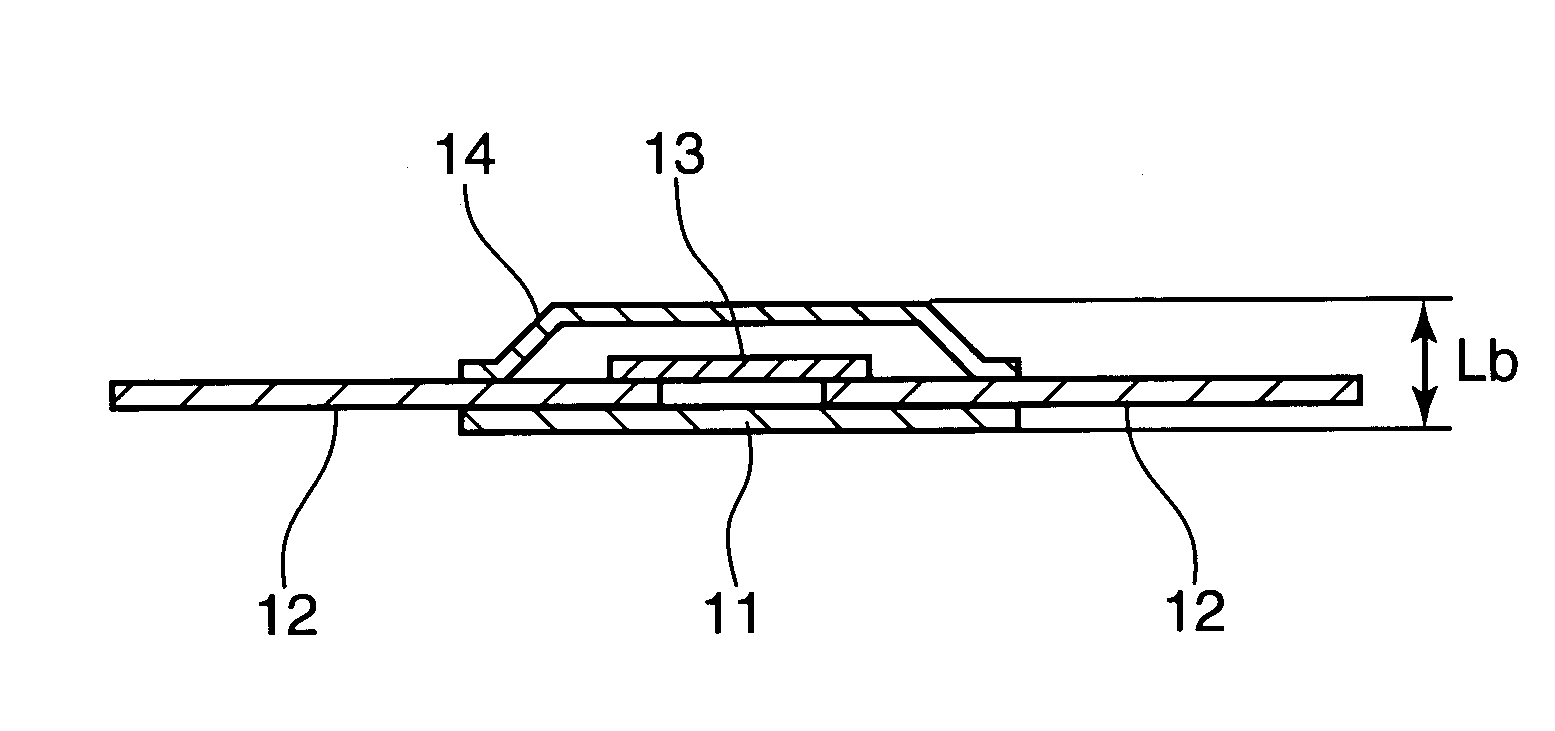
[0057] As shown in FIGS. 1A and 1B, the thin-type thermal fuse comprises: a pair of metal terminals 12; a first insulating film 11 to which the pair of metal terminals 12 are attached; a second insulating film 14 attached to the first insulating film 11 in such a manner as to define a space with the first insulating film 11; and a fusible alloy 13 arranged between the first and second insulating films 11, 14 and connected between the leading end portions of the pair of metal terminals 12.
[0058] The insulating film 11 is a sheet-like insulating film having a monolayer structure, and the pair of metal terminals 12 narrower than the first insulating film 11 are attached to the first insulating film 11. The fusib...
second embodiment
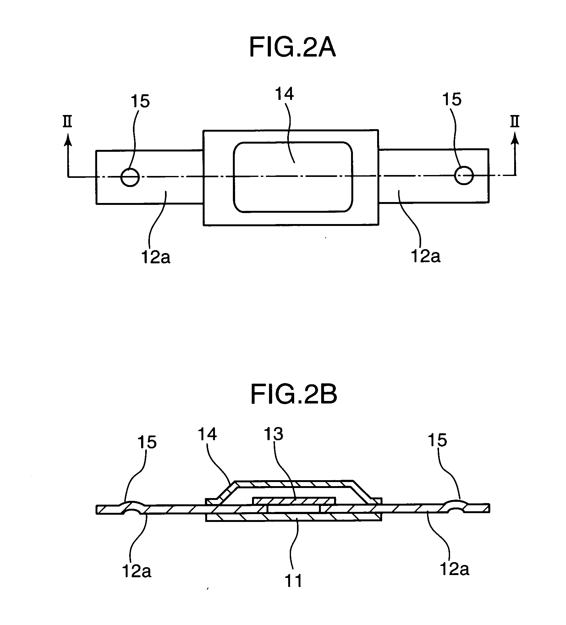
[0089]FIGS. 2A and 2B show the construction of a thin-type thermal fuse according to a second embodiment of the present invention, wherein FIG. 2A is a top view and FIG. 2B is a section along II-II of FIG. 2A. The thin-type thermal fuse shown in FIG. 2 differs from the one shown in FIG. 1 in that a pair of metal terminals 2a are formed to have a strip shape and projections 15 are provided at parts of the metal terminals 12a. Since other points are the same as in the thin-type thermal fuse shown in FIG. 1, no detailed description is given thereon.
[0090] As shown in FIGS. 2A and 2B, the round projections 15 are formed at ends of the metal terminals 12a extending out from a first insulating film 11 and a second insulating film 14. In this embodiment, effects similar to those of the first embodiment can be obtained. In addition, welding strength and welding positions can be stabilized to improve productivity since a welding current can be concentrated if connection is made at the proje...
third embodiment
[0091]FIGS. 3A to 3C are views showing the construction of a thin-type thermal fuse according to a third embodiment of the invention, wherein FIG. 3A is a top view, FIG. 3B is a section along III-III of FIG. 3A, and FIG. 3C is a top view partly in section corresponding to FIG. 3A.
[0092] The thin-type thermal fuse shown in FIG. 3 differs from the one shown in FIG. 1 in that a pair of metal terminals 12b are attached to a first insulating film 11a such that end portions thereof partly project from the lower surface of the first insulating film 11 toward the upper surface thereof as shown in FIGS. 3B and 3C. Since other points are the same as in the thin-type thermal fuse shown in FIG. 1, no detailed description is given thereon.
[0093] As shown in FIGS. 3B and 3C, an inner end portion of each metal terminal 12b is bent to have a substantially wavelike shape, thereby forming a projection 15a at a part of the end portion of the metal terminal 12b, and the first insulating film 11a is f...
PUM
| Property | Measurement | Unit |
|---|---|---|
| weight % | aaaaa | aaaaa |
| weight % | aaaaa | aaaaa |
| length | aaaaa | aaaaa |
Abstract
Description
Claims
Application Information
 - R&D
- Intellectual Property
- Life Sciences
- Materials
- Tech Scout
- Unparalleled Data Quality
- Higher Quality Content
- 60% Fewer Hallucinations
Browse by: Latest US Patents, China's latest patents, Technical Efficacy Thesaurus, Application Domain, Technology Topic, Popular Technical Reports.
© 2025 PatSnap. All rights reserved.Legal|Privacy policy|Modern Slavery Act Transparency Statement|Sitemap|About US| Contact US: help@patsnap.com


