Method and apparatus for through-the-wall motion detection utilizing cw radar

a technology of cw radar and motion detection, applied in the field of through-the-wall sensors, can solve the problems of affecting the detection effect of people, requiring fairly expensive hardware, and having to generate short pulses, etc., and achieve the effect of easy detection of peopl

Inactive Publication Date: 2007-02-01
BAE SYST INFORMATION & ELECTRONICS SYST INTERGRATION INC
View PDF7 Cites 79 Cited by
  • Summary
  • Abstract
  • Description
  • Claims
  • Application Information

AI Technical Summary

Benefits of technology

[0007] In order to obtain a through-the-wall motion detector capable of easily detecting a person within a room, is has been found that one can detect these individuals because they are typically in motion. In order to detect individuals behind a wall, the subject invention employs a simple CW radar with a directional antenna. In one embodiment, the transmitter for this CW radar employs a circulator, which is coupled to a directional antenna so that a CW beam is projected through the wall and into the room. Returns from the CW beam arrive

Problems solved by technology

The difficulty with ultra-wideband approaches is that one has to generate short pulses which requires fairly expensive hardware.
A particular difficulty with ultra wide band is that walls have frequency dependent attenuation.
This results in a distortion of

Method used


Image

  • Method and apparatus for through-the-wall motion detection utilizing cw radar
  • Method and apparatus for through-the-wall motion detection utilizing cw radar
  • Method and apparatus for through-the-wall motion detection utilizing cw radar

Examples


Embodiment Construction

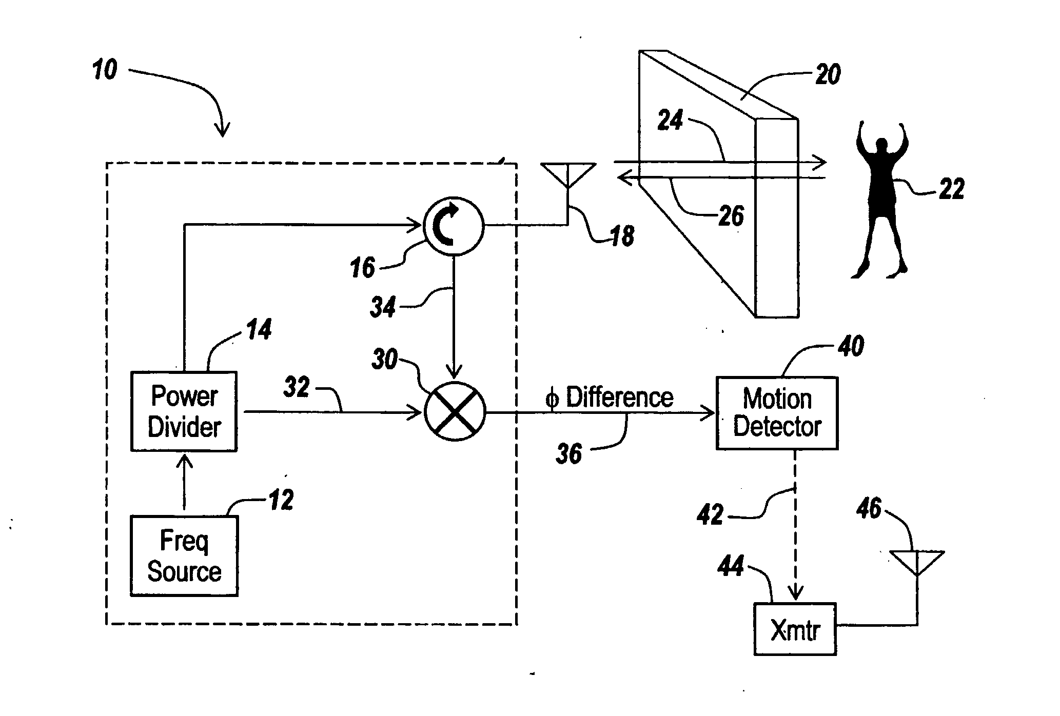
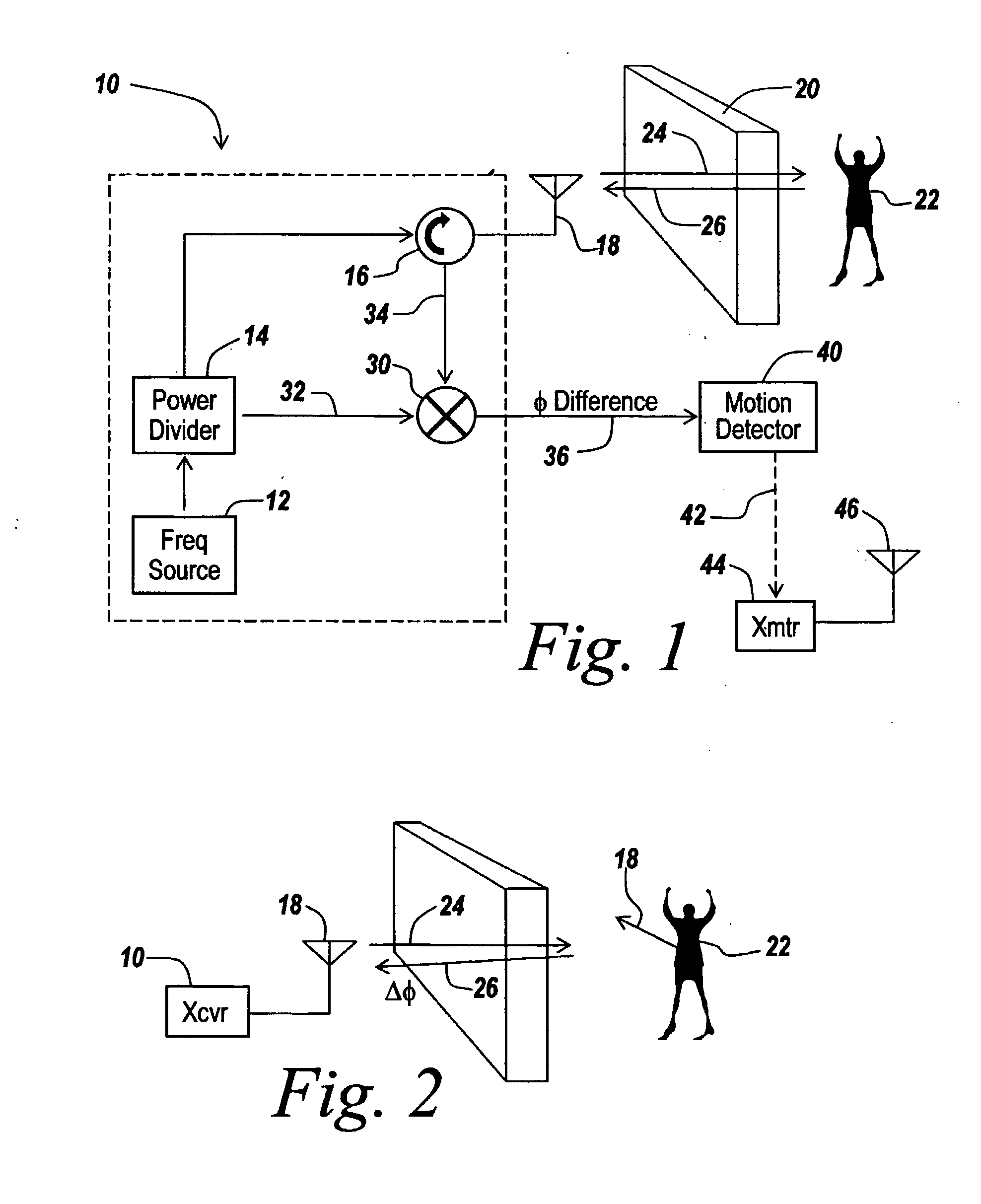
[0023] Referring now to FIG. 1, a CW radar 10 includes a frequency source 12, a power divider 14 and a circulator 16 coupled to an antenna 18. Preferably, the antenna is a directional antenna so as to project all of the energy in a given direction, in this case through a wall 20, so as to be able to ascertain whether an individual 22 exists behind the wall.

[0024] In one embodiment, the radar is a single frequency radar set optimally in one embodiment to 900 MHz, with antenna 18 in one embodiment being a YAGI antenna, with 13 dB forward gain. While a YAGI antenna may be utilized in order to reduce back lobes and yet have a readily portable unit, a flat panel antenna with conductive elements insulated from a ground plane may be used to eliminate back lobes and is lighter and more easily transportable.

[0025] As illustrated, one output of power divider 14 is coupled to circulator 16 coupled to a directional antenna 18 that forms a CW beam as illustrated at 24 which penetrates wall 20....


PUM


Abstract

A CW radar (10) is used to detect motion of objects (22) behind a wall (20) by projecting a radar beam through the wall and by measuring the returns from the objects behind the wall, with a change in the phase difference between the transmitted and received CW signals providing an indication of motion behind the wall and thus the presence of an individual.

Description

RELATED APPLICATIONS [0001] This application claims rights under 35 USC 119(e) from U.S. Application Ser. No. 60 / 537,868 filed Jan. 20, 2004, the contents of which are incorporated herein by reference.FIELD OF THE INVENTION [0002] This invention relates to through-the-wall sensors and more particularly to the use of CW radar to detect motion of objects behind a wall. BACKGROUND OF THE INVENTION [0003] Oftentimes it is desirable to be able to detect individuals within, for instance, a burning building or enemy combatants or troops behind a wall. Moreover, in some instances police can utilize through-wall sensing systems to be able to detect the presence of wanted individuals from a position outside the building. [0004] Through-wall sensing can be used in military operations in urban terrain, for homeland security, for law enforcement and for fire departments. The need to sense behind walls is clear. It will be appreciated that the details of the mission and types of walls or obstruct...

Claims


Application Information

Patent Timeline
IPC IPC(8): G01S13/04G01S13/58G01S13/62G01S13/36G01S13/56G01S13/88
CPCG01S13/36G01S13/888G01S13/88G01S13/56
Inventor ZEMANY, PAUL D.PHIN, ELDONM
Owner BAE SYST INFORMATION & ELECTRONICS SYST INTERGRATION INC
Why Eureka
Try Eureka